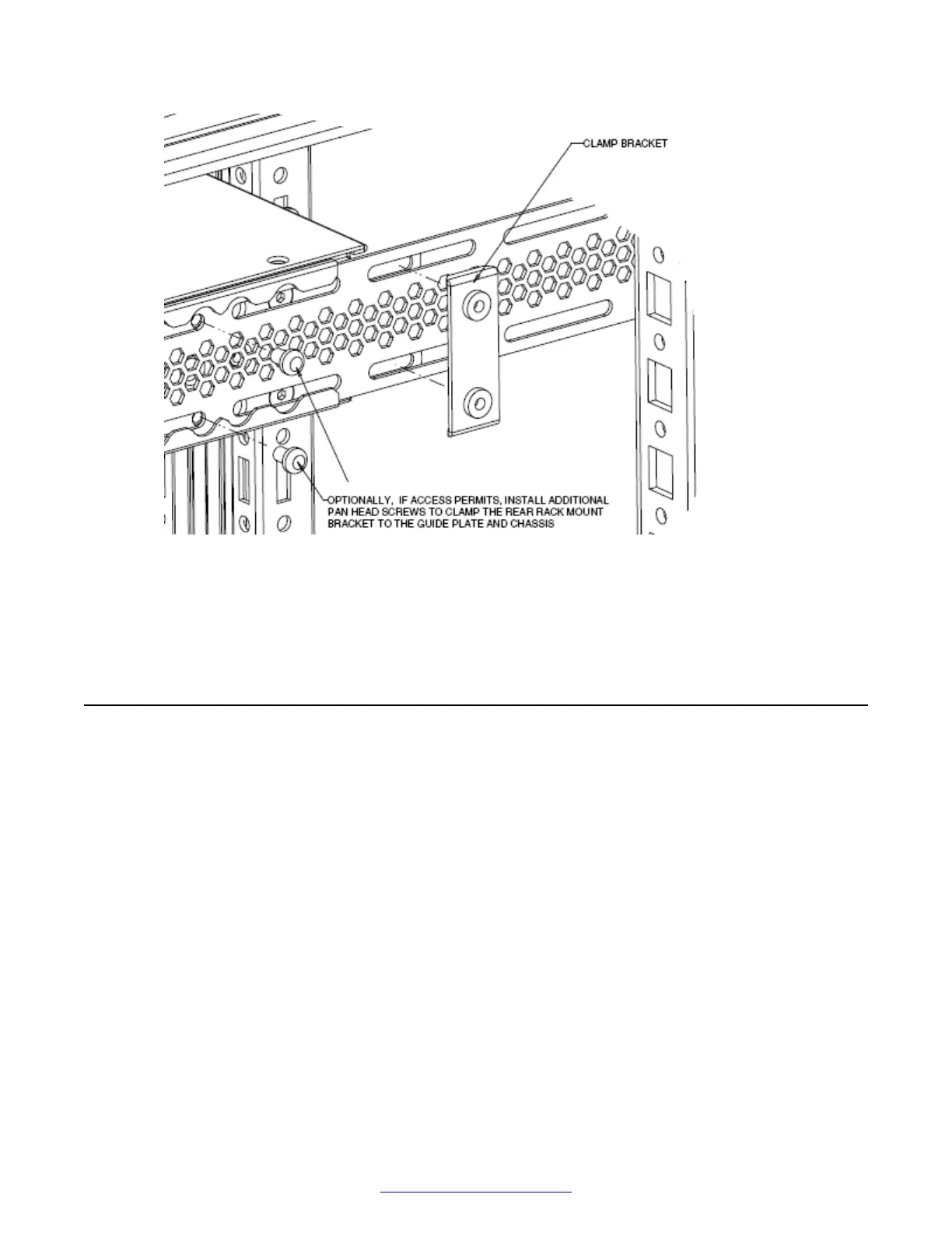
Figure 14: Optional rear bracket screws
You can proceed with the installation by connecting power and network connections to the
switch.
Checking status LEDs to verify switch installation
Perform this procedure to verify the hardware installation and operation of the unit.
The eight status LEDs on the front of the unit indicate the installation and operational status of the
hardware.
Before you begin
Perform the following tasks before checking the status LEDs.
• Install the fan trays and power supplies.
• Install the switch in an equipment rack or on a shelf.
• Connect power to the switch.
Procedure
1. Locate the eight status LEDs on the front of the unit; see the following figure.
Switch installation
34 Installing Avaya VSP 7000 Series August 2014
Comments? infodev@avaya.com

 Loading...