AF942R Remote indicator of system state
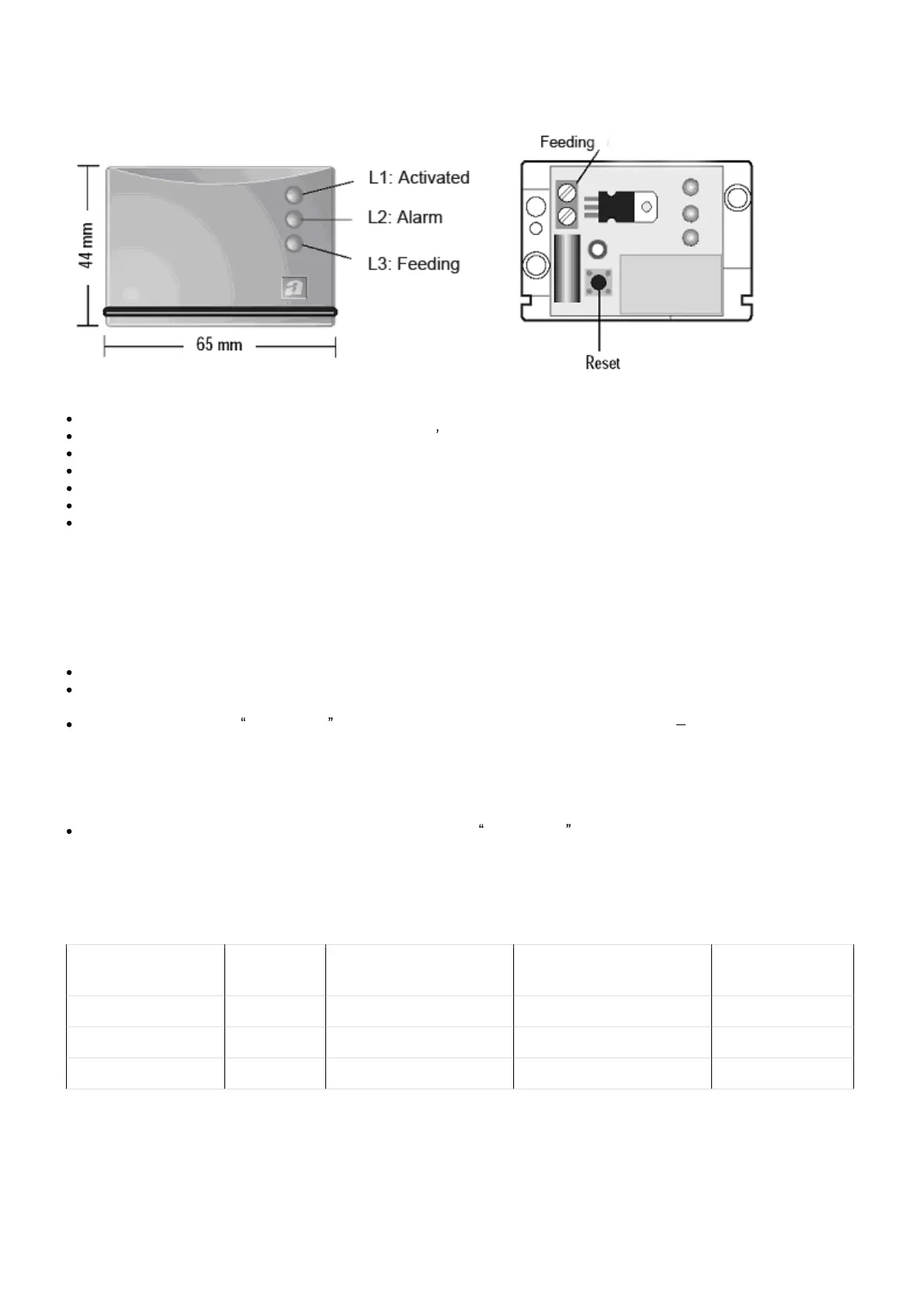
The AF942R remote indicator of the system state shown in the picture, has the following technical characteristics:
Power supply: 8 to 24 V dc or ac 50Hz
Current demand: 5 mA quiescent, 18 mA with LED s on
Enclosure: ABS white (44 x 67 x 19) mm
Installation to the wall by screws; opening for cable input on the bottom
Lid fixed by release on a support
Carrier frequency: 433.92 MHz
Connection nominal range: 30 m under normal conditions in a house (metal walls or anti-seismic structures can
reduce the range. Avoid their installation at less than 2 cm from the metal walls)
Warning: the device is designed for safety low voltage connections. Connection to circuits at hazardous voltage
may be dangerous..
For programming, proceed as follows:
Turn on the power to the system: the LED L3 (green) will switch on.
Press the internal reset push-button; LED L1 (green) and L2 (red) will switch on alternatively: the code learning
sequence is carried out.
Transmit the signal of disactivated from the control panel (control panel disactivated OFF) by disactivating
the previously activated control panel by the remote control.
NOTE: each time a disactivation is carried out by means of the remote control, the control panel transmits the
signal of disactivated .
Once the system state indicator has received the signal disactivated from the control panel, it stores the code
linking it to the control panel and so it is ready to operate.
Concerning the operation of the device, take note of the following:
The device receives the signals of activated , disactivated and alarm from the control panel and transmits the
signals on the front panel as described below (see Fig. 5 for LED description).
LED COLOUR ON OFF FLASHING
L1 (activated) Green Control panel activated Control panel disactivated --
L2 (alarm) Red -- No alarm Alarm
L3 (feeding) Green Power on Power off --