Chapter 2: Hardware Overview and Stand-Alone Operation 5
Chapter 2: Hardware Overview and Stand-
Alone Operation
This chapter describes the Pro Tools | PRE front and back panels, and includes instructions for using its
switches, indicators, and connectors for Stand-alone mode operation. To use PRE in Remote mode (remote
control of PRE by Pro Tools or a dedicated control surface), see Chapter 3, “Remote Operation.”
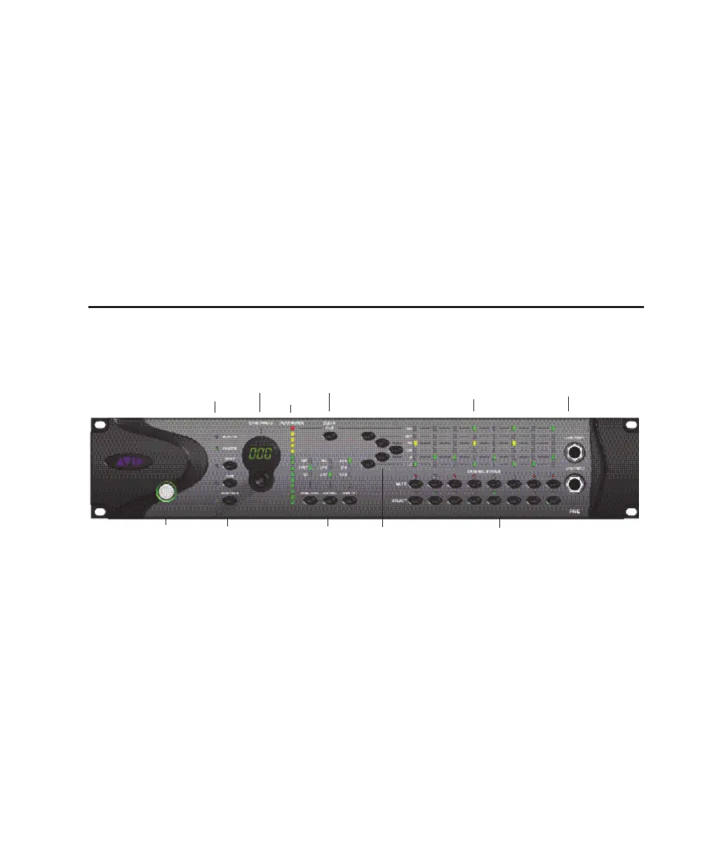
Pro Tools | PRE Front Panel
Pro Tools | PRE has the following front panel switches, indicators, and connectors:
Power Switch and LED Ring
This switch turns PRE on and off. When lit
(green), the LED ring around the power switch in-
dicates that the unit is switched on.
By default, PRE powers up in Stand-alone mode.
In this mode, controls can be adjusted from the
front panel or remotely. The Remote “Lock-Out”
LED is unlit (signifying Remote Lock-Out mode is
inactive).
At power up, PRE units default to the last settings
they had at power down, with the exception of Re-
mote Lock-Out mode.
Activity LED
When lit (green), this LED indicates MIDI data is
being received by PRE.
Pro Tools | PRE front panel
Activity and Remote LEDs
Channel Select and
Mute switches and
LEDs
Shift, Oscillator, and
MIDI Chan switches
Line/Inst 1 and 2
Gain/Param
Power switch
and LED ring
Peak Meter
Clear Clips
Peak Hold, Source,
and Input Impedance
Signal Present/Clip, 48V, Insert, Pad,
Phase, and High-Pass Filter indicators
48V, Insert, Pad, Phase,
and High-Pass Filter