S6L Control Surface RAM Expansion 12
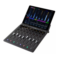
6 Using a #2 Phillips screwdriver, loosen the captive screws.
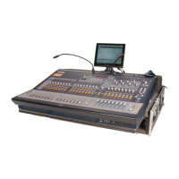
7 If cables in your unit are bound with a cable tie similar to that shown below, cut the cable tie (this will allow the SBC Tray to
be removed).
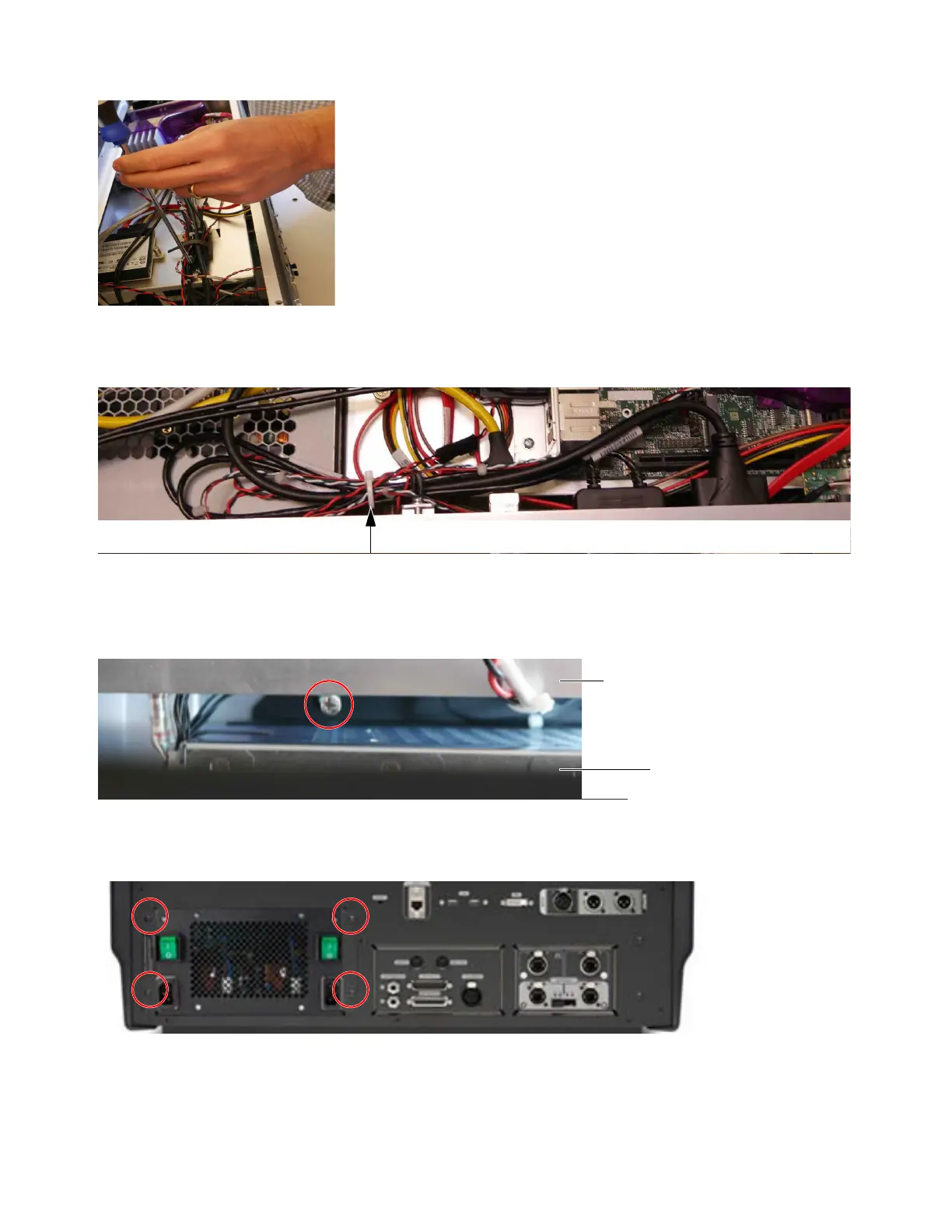
8 (S6L-16C Only) Move the PSU out of the way to be able to remove the SBC Tray by doing the following:
• Using a 12-inch magnetic tip #2 Phillips screwdriver, remove the two fasteners that secure the lower back of the PSU to the
bottom of the control surface chassis (between the lower back of the PSU and the chassis interior wall).
• Using a 2.5mm Hex driver, stand at the back of the control surface and remove the four fasteners that secure the PSU Bay to
the back of the S6L chassis.
• From inside the chassis, push the PSU assembly out far enough to be able to grab the flanges then carefully pull the PSU as-
sembly almost all the way out of the chassis (you do not need to remove it). Use a block or similar to support the PSU
assembly.
Figure 23. Loosening one of the captive screws
Figure 24. Cable tie
Figure 25. One of the two inner screws that secure the PSU to the bottom of the control surface chassis
Figure 26. PSU fasteners to remove
 Loading...