1. Make sure the safety lanyard is connected to the camera.
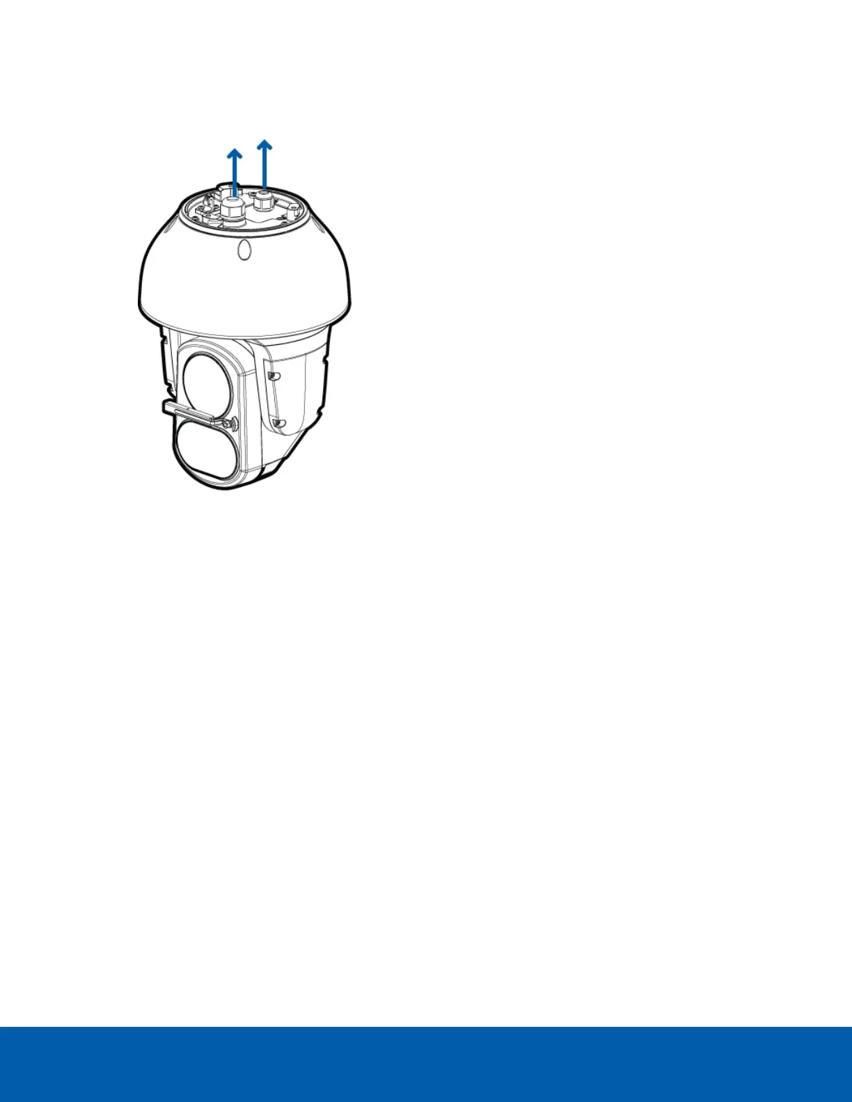
2. Remove the sealing gland caps from the top of the camera.
3. If there are external input or output devices that need to be connected to the camera (for example:
door contacts, relays, analog video, speakers, etc.), connect the devices to the camera I/O connector
cable.
4. Connect power using one of the following methods:
l
95W PoE Injector (POE-INJ2-95W) — Connect an Ethernet network cable to the injector.
l
60W PoE Injector (POE-INJ2-60W) — Connect an Ethernet network cable to the injector.
l
Cisco® UPoE capable switch, supporting 60 W over 4 pairs. Note that the Cisco switch must be
configured with the Force Four Pair option enabled.
l
External Power — Connect a 24V DC or 24V AC (RMS) auxiliary power source that supports up
to 75 W or 105VA.
For more information, see Connecting to Power and External Devices on page20.
5. Thread the Ethernet cable into the cable gland.
a. Drill a hole through the center of the provided cable gland that is slightly smaller in diameter
than the Ethernet cable.
Do not cut or slice the cable gland. This may make it possible for water to enter the camera, and
could void the warranty.
Connecting Cables 11
 Loading...