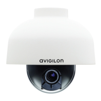
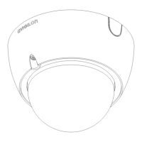
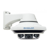
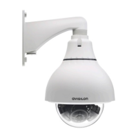
9. Connect the safety lanyard from inside the NPT mount adapter to the anchor on the dome camera.
Connecting Cables
Refer to the diagrams in the Overview section for the location of the different connectors.
To connect the cables required for proper operation, complete the following:
1. Make sure the safety lanyard is connected to the dome camera.
2. If there are external input or output devices that need to be connected to the camera (for example: door
contacts, relays, speakers, etc), connect the devices to the camera I/O connector cable.
3. Connect power using one of the following methods:
l Power over Ethernet (PoE) Class 3 or PoE Plus Class 4 — Connect a PoE compliant injector or
switch to the Ethernet network cable.
l External Power — Connect an external “Class 2” or “LPS” or “Limited Power Source” with output
rated 24VAC +/- 10%, 37VA minimum or 24VDC +/- 10%, 26W minimum.
For more information, see Connecting External Power on page17.
Tip: When installing in cold environments, use PoE Plus Class 4 or external power to defrost or
defog the dome bubble more quickly.
4. Connect a network cable to the Ethernet port (RJ-45 connector).
The Link LED will turn on once a network link has been established.
5. Check that the Connection Status LED indicates the correct state. For more information, see LED
Indicators on page19.
Securing the Dome Camera
After the cable connections have been made, secure the dome camera to the mount.
Connecting Cables 13
 Loading...
