11
English
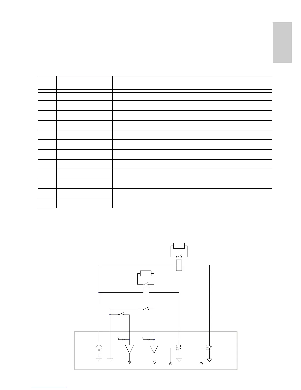
Connecting to External Devices
External devices, including audio and video devices, are connected to
the camera through the I/O cable. The pinout for the I/O connector is
shown in the following table.
NOTE: The 12 V connection can be used to energize a relay coil with
up to 50 mA. If more than 50 mA is required, an external
power supply up to 25 VDC at 120 mA can be used.
Table: External I/O Connector
Pin Wire Color Description
1 White Audio/video analog ground return
2 Brown Analog audio input
3 Green Analog audio output
4 Yellow Analog video output
5 Grey Relay ground return
6 Pink Relay output 1
7 Blue Relay output 2
8 Red Relay input 1
9 Orange Relay input 2
10 Dark Red +12 VDC, 50 mA max. output for relay drive
11 Black Not connected
12 Purple
GND
3.3V
GND
MAX 50 mA
GND
12 V
MAX 120 mA
3.3V
GND
MAX 120 mA
GND
RELAY
RELAY
DARK RED
GREY
RED
ORANGE
PINK
BLUE
SWITCH
SWITCH
IN1
IN2
OUT1
OUT2
 Loading...