Page 10
6. Repeat for each call box until all call boxes in the loop have been terminated.
NOTE: Maximum wire run length between each Call Box is 200 feet.
NOTE: Maximum wire run length for a single loop is 1200 feet.
NOTE: A maximum of 24 Call Boxes can be connected on a single loop.
7. Connect remaining call boxes to L2B following the steps detailed in the BOSS to Call Box
wiring section on page 8 and the Call Box to Call Box wiring section on page 9.
NOTE: Either connection on the call box can be used for input/output. It is recommended to
always use the same port on each call box for the input and the other as the output for
simplication purposes.
8. Once all call boxes have been terminated, use the screws and torx bit included with the call
boxes to mount the faceplate to the back box.
Dedicated Phone Line Wiring
1. Connect the analog phone line or equivalent connection (cable modem, VoIP gateway, or
cellular device) to the 2-pin screw terminal connector then connect it to the External Line 1
connection. The phone line input is not polarity sensitive.
NOTE: If using an external phone line with the system, it is recommended the line is veried and
functional before connecting to the system. The phone line should have voltage, as well as
dial tone. It is not recommended to use “ring-down” style phone lines with this system.
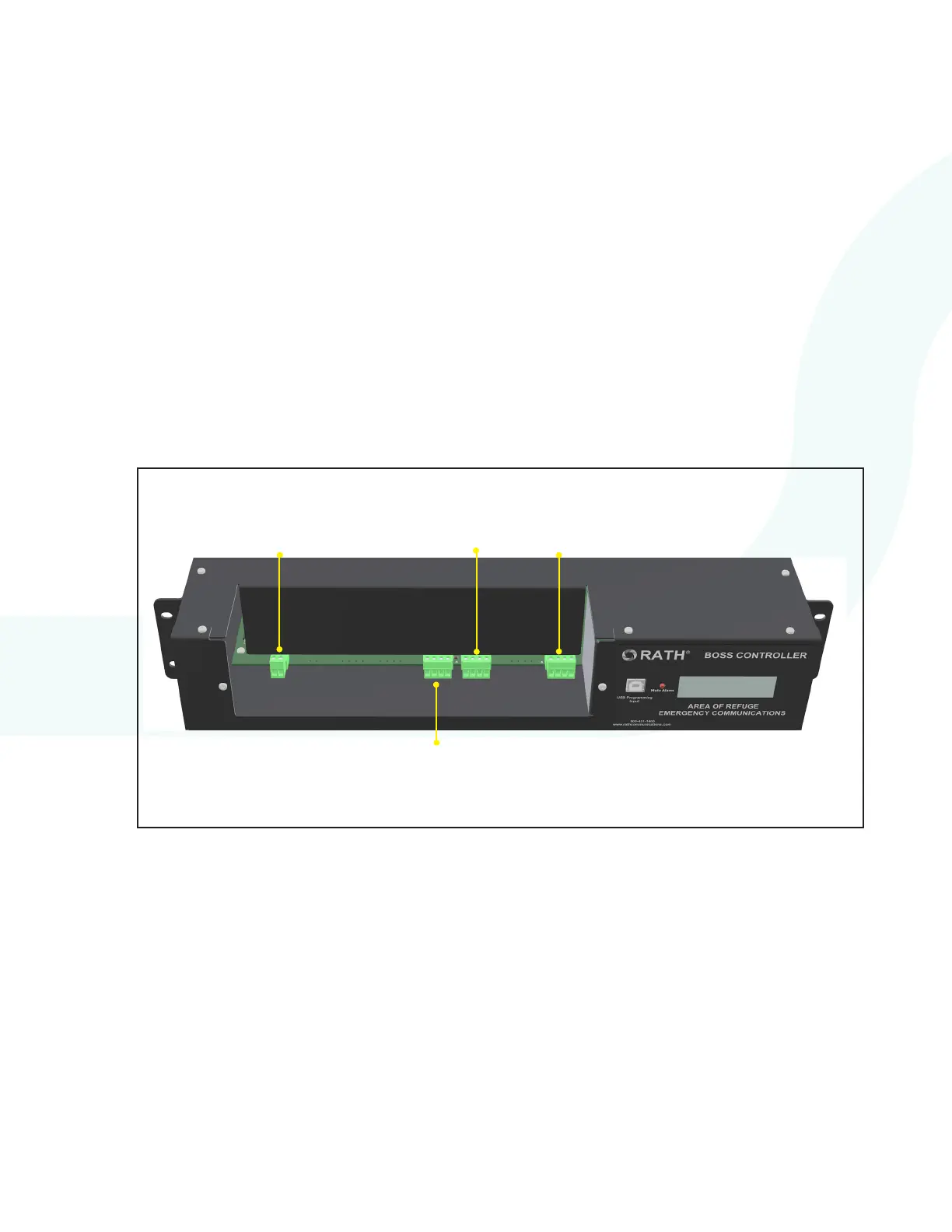
EXTERNAL
LINE 1
L2B
LOOP 2
CALL BOX
25-32
L2A
LOOP 1
CALL BOX
1-24
L1A
CALL
COMMANDER