Page 9
6. Once both ends of the cable have the 4-pin loop connectors securely terminated, plug the
end landed at the rst call box into either of the green terminal plugs on the back of the rst
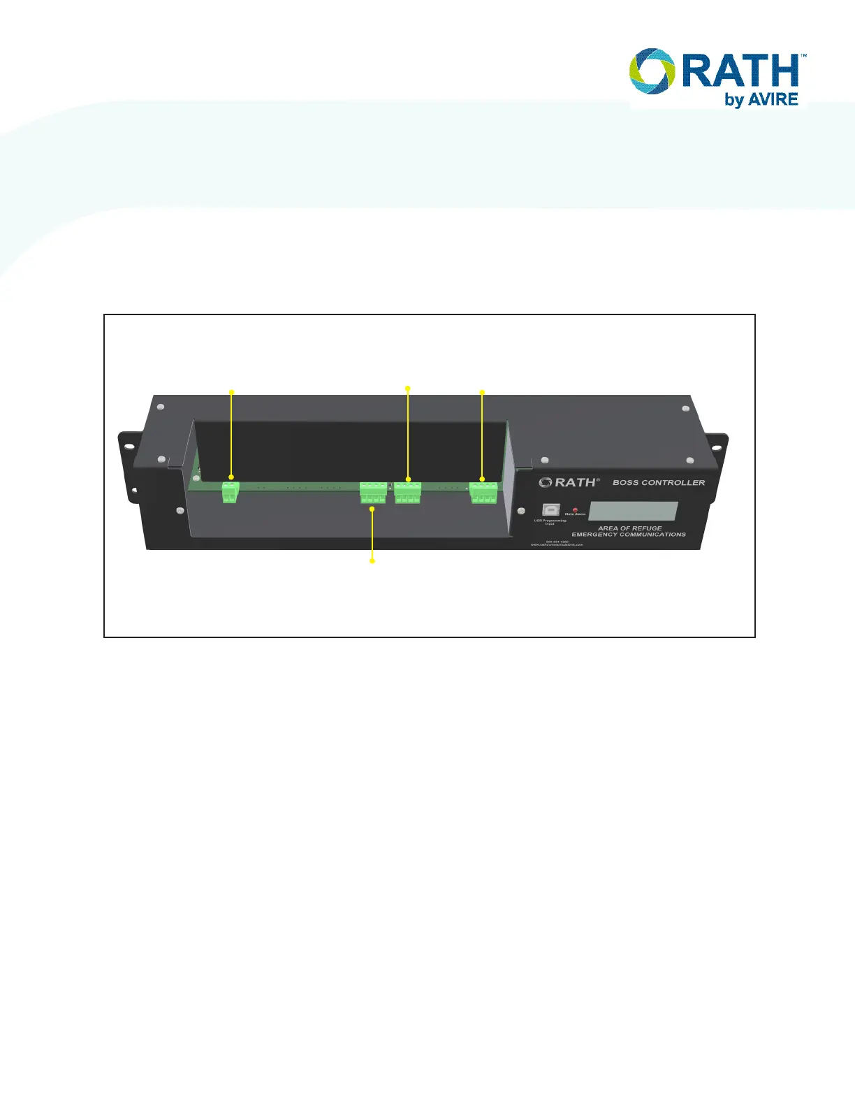
Call Box. Then, plug the side landed at the BOSS controller into port L2A on the BOSS. See
below for detailed port labels on the BOSS.
NOTE: Either connection on the call box can be used for input/output. It is recommended to
always use the same port on each call box for the input and the other as the output for
simplication purposes.
Call Box to Call Box Wiring
1. Run an 18/4 cable from the rst Call Box to the next Call Box in the loop.
2. On both ends of the 18/4 cable, strip back and expose 1/4” of wire on the individual
conductors of the 18/4.
3. Route cable through applicable knock-outs done during back box mounting.
4. Screw the four wires from the 18-4 cable into the provided 4-pin loop connector following
same pin on page 8. Verify the wires are seeded fully into the connector and the screw
terminals are rmly tightened down before moving on. Repeat for both ends of the cable.
5. Once both ends of the cable have the 4-pin loop connectors securely terminated, plug the
end landed at the rst call box into either of the green terminal plugs on the back of the rst
call box. Then, plug the other end into either port on back of the second call box in the loop.
EXTERNAL
LINE 1
L2B
LOOP 2
CALL BOX
25-32
L2A
LOOP 1
CALL BOX
1-24
L1A
CALL
COMMANDER