Page 8
BOSS to Call Box Wiring
1. Install the Call Boxes:
a. Surface Mount: Remove any applicable knockouts in the back box to align with conduit
ran to the call box mounting location. Mount the back box included with the surface
mount call box in the building owner or AHJ’s specied location using appropriate
mounting hardware. Repeat for all call boxes.
b. Flush Mount: Remove any applicable knockouts in the back box to align with conduit
ran to the call box mounting location. Mount the ush mount back box (RATH part
number: RP7700504) in the call box cutout in the wall. Repeat for all call boxes. Flush
mount back boxes are sold separately and do not come with the call box.
2. Run an 18/4 cable from the BOSS to the rst Call Box.
NOTE: This cable provides communication and power. No additional power is required.
NOTE: Maximum wire length to the rst Call Box is 200 feet.
3 On both ends of the 18/4 cable, strip back and expose 1/4” of wire on the individual
conductors of the 18/4.
4. Route the cable through applicable knock-outs done as a part of step 1.
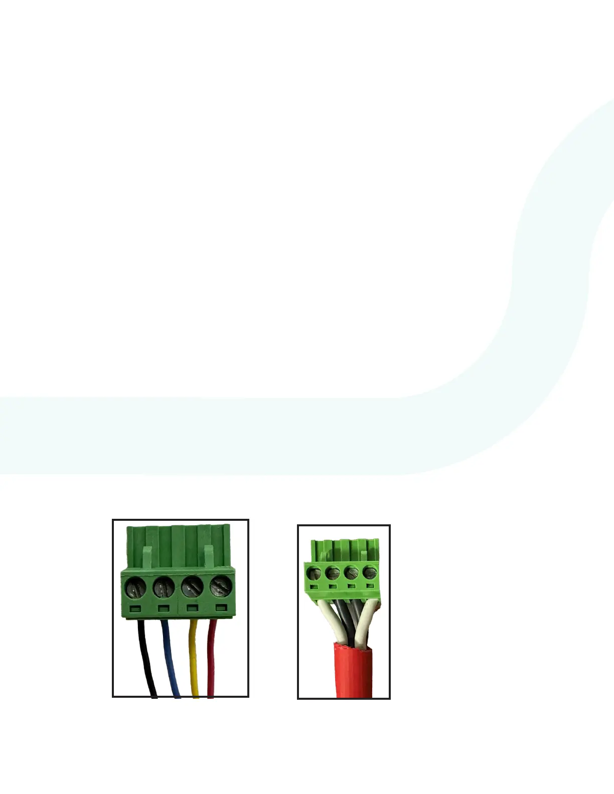
5. Screw the 4 wires from the 18/4 cable into the provided 4-pin loop connector following
the wire scheme below. Verify the wires are seated fully into the connector and the screw
terminals are rmly tightened down before moving on. Repeat for both ends of the cable.
If using RATH
®
66120 cable, follow
the “1” and “2” printed on the
insulation jacket around the wire.
Recommended order is 1 White, 1
Black, 2 Black, 2 White.
Power +
Power -
Data 1
Data 2
P/N: 66120
P/N: RP7500094B
7. If using a surface or ush mount Call Commander, install the cabinet faceplate back onto
the back box and secure using the provided Hex screws and Allen wrench.