If using RATH
66120 cable, fol-
low the “1” and “2” printed on the
insulation jacket around the wire.
Recommended order is 1 White, 1
Black, 2 Black, 2 White.
Power +
Power -
Data 1
Data 2
P/N: 66120
P/N: RP7500094B
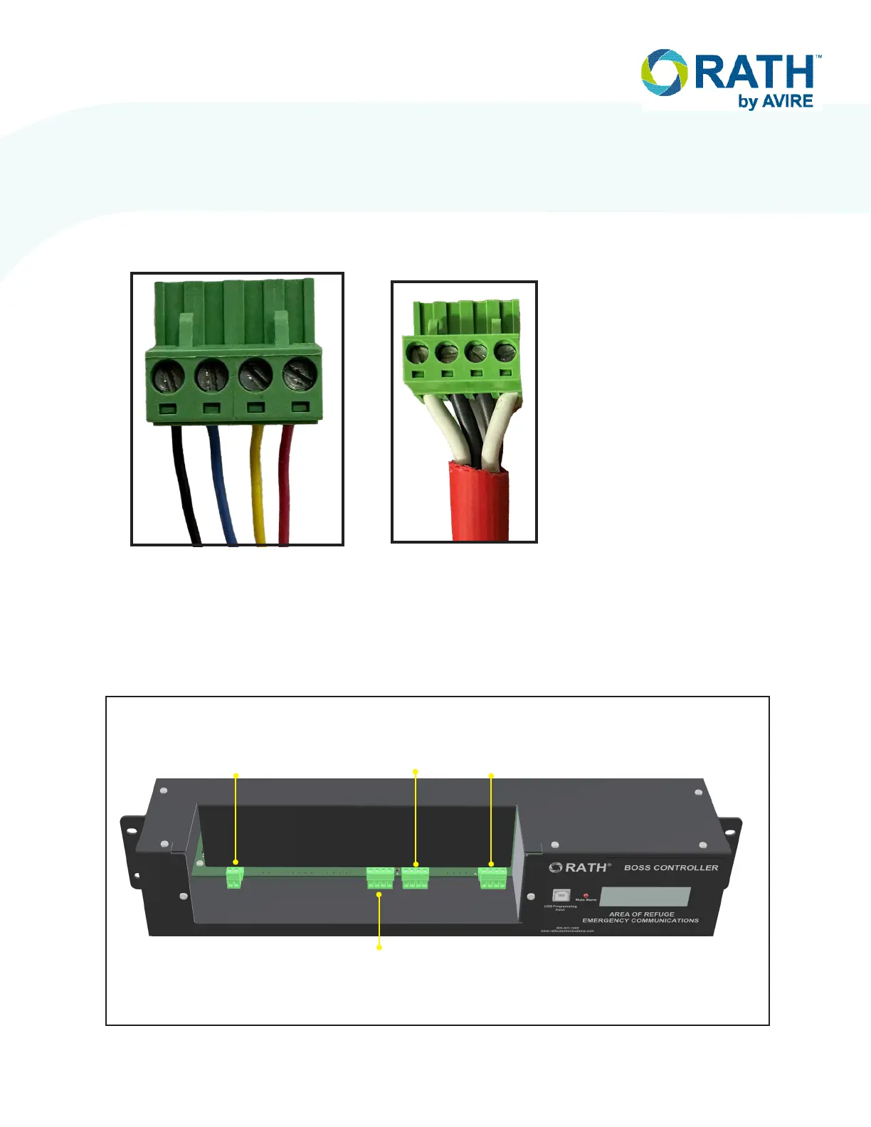
6. Once both ends of the cable have the 4-pin loop connectors securely terminated, plug the
end landed at the Call Commander into either of the green terminal plugs on the back of the
Call Commander. Then, plug the side landed at the BOSS controller into port L1A on the
BOSS. See below for detailed port labels on the BOSS.
4. Route the cable through applicable knock-outs done as a part of step 1.
5. Screw the 4 wires from the 18/4 cable into the provided 4-pin loop connector following
the wire scheme below. Verify the wires are seated fully into the connector and the screw
terminals are rmly tightened down before moving on. Repeat for both ends of the cable.
Page 7
EXTERNAL
LINE 1
L2B
LOOP 2
CALL BOX
25-32
L2A
LOOP 1
CALL BOX
1-24
L1A
CALL
COMMANDER