17 TECHNICAL APPENDIX
This section provides all the technical explanations, and the connection pin outs to and from the Macrotel X1 and
Macrotel X2 device. Always refer to this technical appendix for connections and connection procedures. In case of
differences between the documentation below and the hardware device please contact Axel Technology at the numbers
and e-mail addresses shown at the end of this manual. Our technical and assistance department will be pleased to help
you!
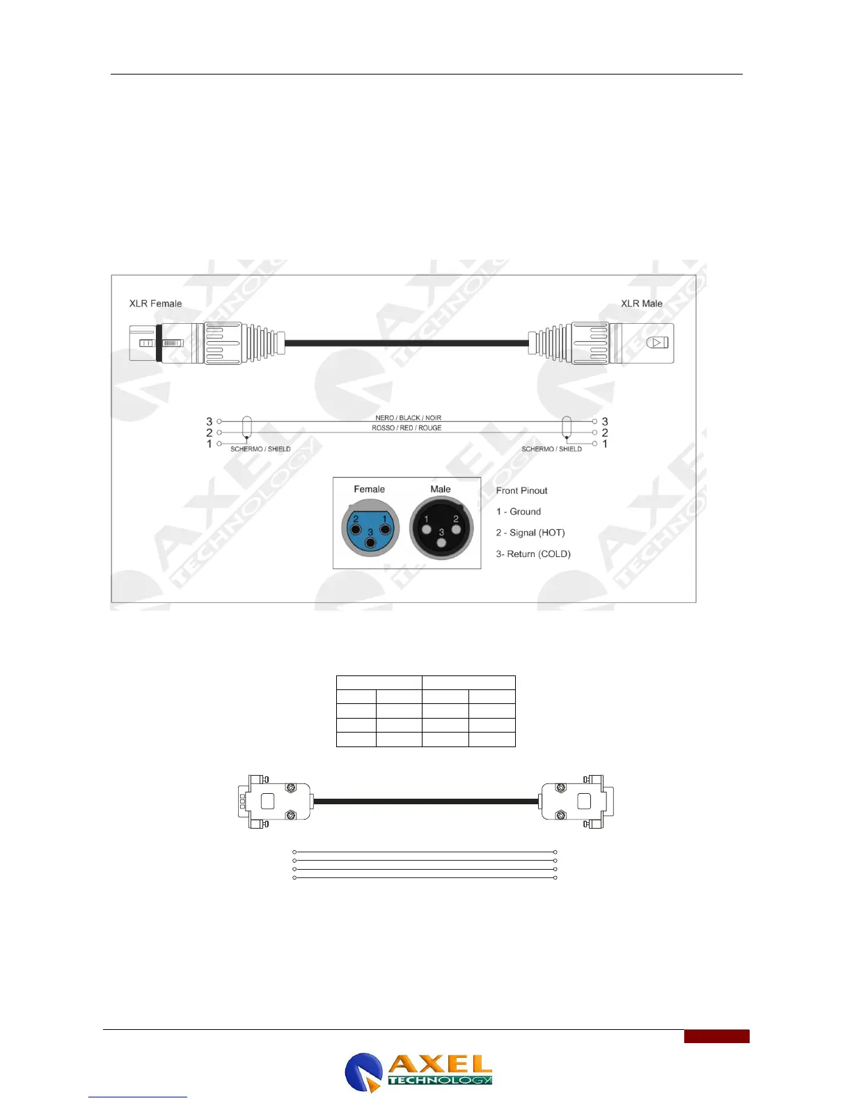
17.1 APPENDIX A – BALANCED AUDIO CONNECTION AND PINOUT
Balanced Audio connection diagram with balanced XLR for Analog audio input and output (Left+Right) and AES/EBU
digital audio input and output.
17.2 APPENDIX B – SERIAL CONNECTION E PINOUT
A standard Pin-to-Pin serial cable is required for the PC connection, not a CROSSOVER one. For a correct connection
the cable must not be more than 20 m long. Ports 2 and 3 use only the Tx, Rx and GND for the PC connection while port
1 also has the DTR (Data Terminal Ready) for modem connection. The port connection speed must coincide with the
speed of the port of the Macrotel X device and of the PC’s serial port.
 Loading...