AXIS 211M - I/O Terminal Connector
37
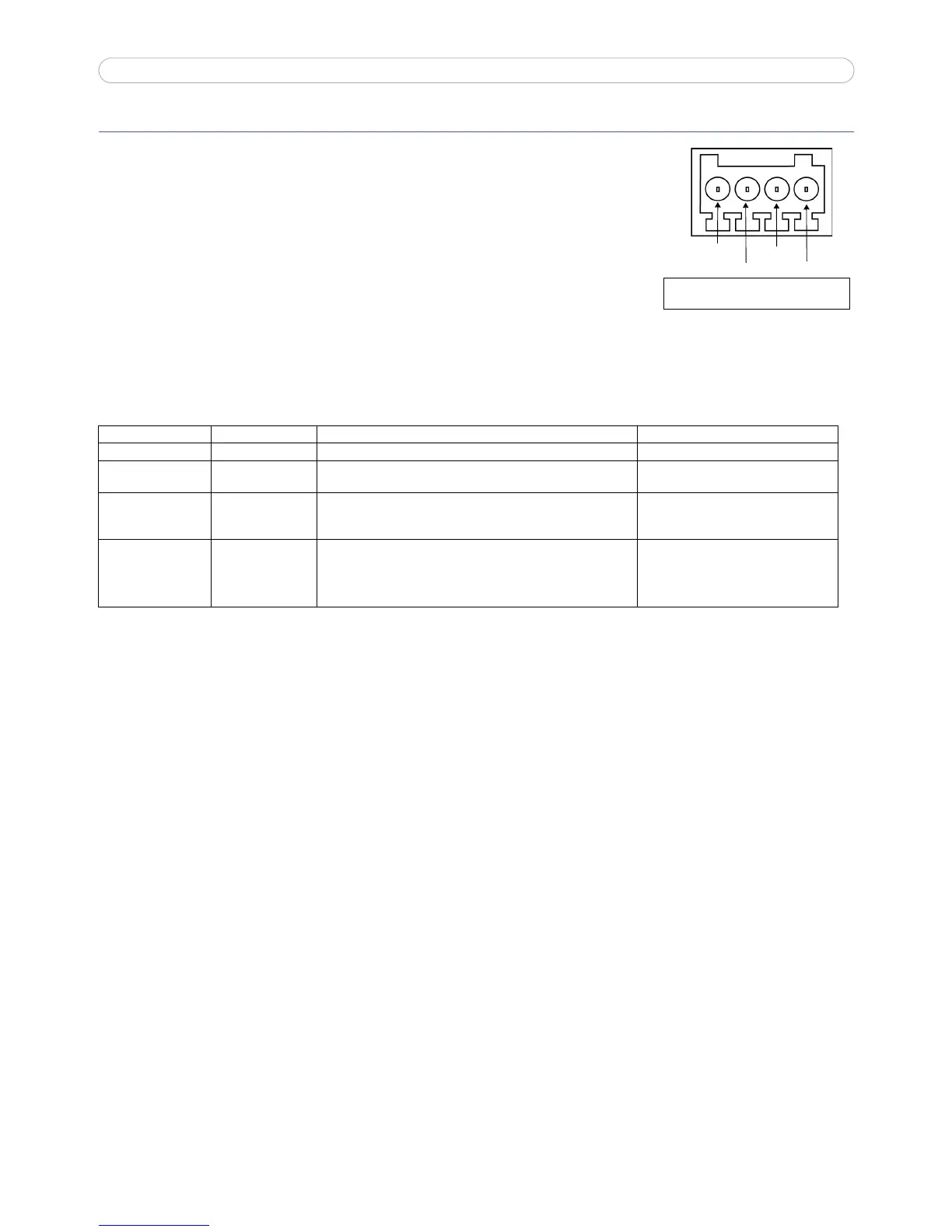
I/O Terminal Connector
The I/O terminal connector is used in applications such as motion detection,
event triggering,
time lapse recording and alarm notifications. It provides the
interface to:
• 1 transistor output - For connecting external devices such as relays and
LEDs. Connected devices can be activated by the AXIS VAPIX API, out
-
put buttons on the Live View page or by an Event Type. The output
will show as active (shown under Event Configuration > Port Status) if
the alarm device is activated.
• 1 digital input - An alarm input for connecting devices that can toggle
between an open and closed circuit, for example: PIRs, door/window contacts, and glass break detec
-
tors. When a signal is received the state changes and the input becomes active (shown under Event
Configuration > Port Status).
• Auxiliary power and GND.
Function Pin number Notes Specifications
GND 1
5V DC Power 2 Can be used as an alternative power supply (7-20VDC) or to power
auxiliary equipment +5VDC (100mA).
Max load = 100mA
Digital Input 3 Connect to GND to activate, or leave floating (or unconnected) to
deactivate.
Must not be exposed to voltages greater
than
20VDC
Transistor Output 4 Connects to GND when activated. If used with an external relay, a
diode must be connected in parallel with the load for protection
against voltage transients.
Max load =100mA
Max voltage = 24VDC
(to the transistor)