AXISP13-ESeries
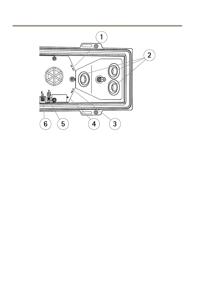
1
Networkconnector(PoEOUT,connectedatdelivery)
2
Cableholes
3
Networkconnector(PoEIN)
4
LEDindicator
5
ArcticTemperatureControlswitch
6
Alarmoutput(connectedatdelivery)
1.OptionallyinsertanSDmemorycard(notincluded)intotheSDcardslot.Astandardor
highcapacitySDcardisrequiredtostoreimageslocallyinthecamera.
2.Optionallyconnectexternalinput/outputdevices.SeeConnectorsonpage16for
informationontheconnectorpins.SeeRoutetheNetworkCableThroughtheCableHole
onpage19forinformationonpreparingthenetworkcable.Routethecablesthrough
thecableholesintothebottomcoverandtothecamera.
3.Connectthecameratothenetworkusingashieldednetworkcableandusingthe
networkconnector(PoEIN)onthebottomcover.ThenetworkcableandtheI/Ocable
betweenthebottomcoverandthecamera,arealreadyconnectedatdelivery.
4.CheckthattheindicatorLEDsindicatethecorrectconditions.SeeLEDIndicatorson
page12forfurtherdetails.
AccesstheProduct
AXISIPUtilityandAXISCameraManagementarerecommendedmethodsforndingAxisproducts
onthenetworkandassigningthemIPaddressesinWindows®.Bothapplicationsarefreeandcan
bedownloadedfromwww.axis.com/techsup
22