AXISP33/-VSeriesFixedDomeNetworkCamera
ConnectionDiagrams
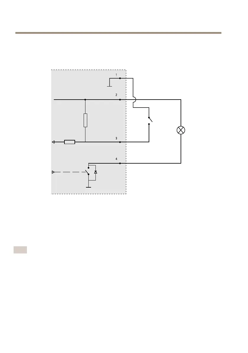
I/OConnector
1
0VDC(-)
2
DCoutput3.3V,max50mA
3
Digitalinput0tomax40VDC
4
Digitaloutput0tomax40VDC,opendrain,100mA
InstalltheHardware
Note
•ThisAxisproductcanbemountedwiththecablesroutedthroughoralongthewall.
•Thisproductcanbettedwithametalconduitforprotectingthecablingwhenthe
cablesareroutedalongthewall.
16
 Loading...