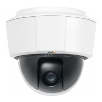
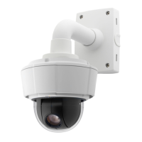
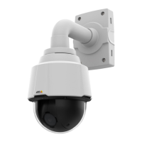
AXIS P5534 PTZ Dome Network Camera
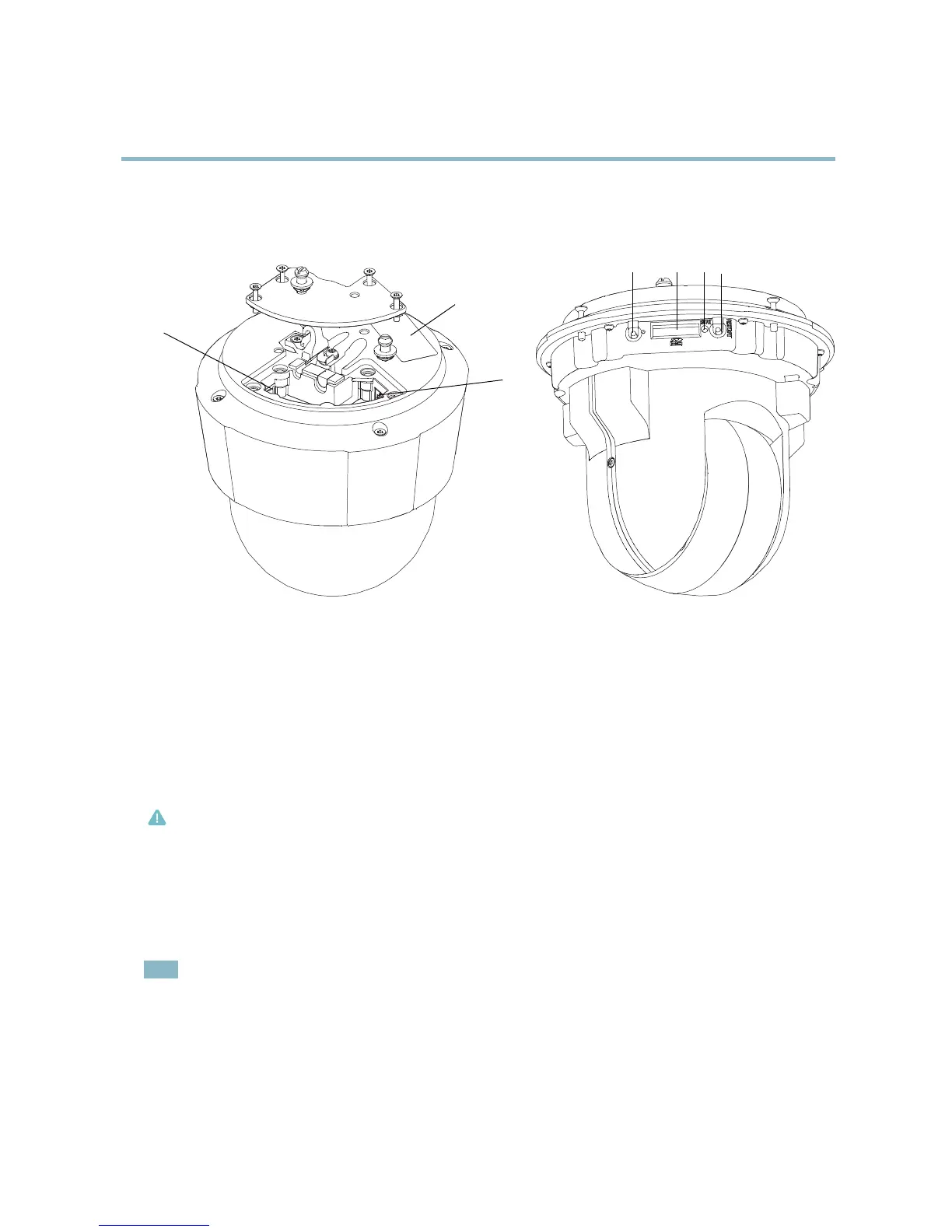
Hardware overview
Hardware overview
65
74
1
2
3
1
Part number (P/N) & Serial number (S/N)
2
Network connector (High PoE)
3
Multi-connector
4
Control button
5
SD memory card slot
6
Status LED indicator
7
Restart button
Connectors
Network connector - RJ-45 Ethernet connector. Supports Power over Ethernet Plus (PoE+) IEEE 802.3at. Use the supplied m idspan.
Caution
Due to local regulations or the environmental
and electrical conditions in which the product is to be used, a shielded network
cable (STP) may be appropriate or required. Any network cables that are routed in outdoor environments or similar shall be
shielded (STP) and intended for their specific use. Make sure that the midspan is properly grounded. See Electromagnetic
Compatibility (EMC) for regula
tory re quirements.
SD card slot - A standard or high-capacity SD card (not included) can be used for l ocal recording with r emovable storage. For
instructions on how to insert and remove an SD card, please refer to the Installation Guide.
Note
Before removal, the SD card should be unmounted to prevent corruption of recordings. To unmount the SD card, go to Setup
>SystemOptions>Storage>SDCardand click Unmount.
Control but
ton - The control button is used for:
• ConnectingtoanAXISVideoHostingSystemservice.Seepage 40. To connect, press and hold the button for about
1 second until the Status LED flashes green.
5