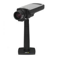
AXISQ1604-ENetworkCamera
HardwareOverview
15.
Bracketscrews(4x)
16.
Bracketadapter
17.
Networkcable(routethroughwallbracket).Cablenotincluded
18.
Wallbracket
19.
Bracketadjustmentscrew
ColdStartupDelaySwitch
TheColdStartupDelayswitch,whenturnedon,controlshowthecamerarestartsafterapowercut,whentemperaturesarebelow
0°C(32°F).Thecameraisrstheatedtoapproximately0°C(32°F)beforeitinitializes.Thispreventsdamagetocameraparts
sensitivetosub-zerotemperatures.
ConnectorsandButtons
Fortechnicalspecications,seepage60.
NetworkConnector
RJ45Ethernetconnector.SupportsPoweroverEthernet(PoE).
NOTICE NOTICE
NOTICE
Theproductshallbeconnectedusingashieldednetworkcable(STP).Allcablesconnectingtheproducttothenetworkswitch
shallbeshielded(STP)andintendedfortheirspecicuse.Makesurethatthenetworkswitchisproperlygrounded.For
informationaboutregulatoryrequirements,seeRegulatoryInformation,onpage2.
I/OConnector
Usewithexternaldevicesincombinationwith,forexample,tamperingalarms,motiondetection,eventtriggering,timelapserecording
andalarmnotications.Inadditiontothe0VDCreferencepointandpower(DCoutput),theI/Oconnectorprovidestheinterfaceto:
•Digitaloutput–ForconnectingexternaldevicessuchasrelaysandLEDs.Connecteddevicescanbeactivatedbythe
VAPIX®ApplicationProgrammingInterface,outputbuttonsontheLiveViewpageorbyanActionRule.Theoutputwill
showasactive(shownunderSystemOptions>Ports&Devices)ifthealarmdeviceisactivated.
•Digitalinput–Analarminputforconnectingdevicesthatcantogglebetweenanopenandclosedcircuit,forexample:
PIRs,door/windowcontacts,glassbreakdetectors,etc.Whenasignalisreceivedthestatechangesandtheinputbecomes
active(shownunderSystemOptions>Ports&Devices).
Note
TheI/Oconnectorisconnectedtothehousing(fan/heater)ondelivery.Inthecaseofafanorheatererror,aninputsignal
willbetriggeredinthecamera.Setupanactionruleinthecameratocongurewhichactionthesignalshalltrigger.For
informationabouteventsandactionrules,seeEvents,onpage37.
PowerConnector
2-pinterminalblockforpowerinput.UseaSafetyExtraLowVoltage(SELV)compliantlimitedpowersource(LPS)witheitherarated
outputpowerlimitedto≤100Woraratedoutputcurrentlimitedto≤5A.
AudioConnector
TheAxisproducthasthefollowingaudioconnectors:
•Audioin(pink)–3.5mminputforamonomicrophone,oraline-inmonosignal(leftchannelisusedfromastereosignal).
•Audioout(green)–3.5mmoutputforaudio(linelevel)thatcanbeconnectedtoapublicaddress(PA)systemoran
activespeakerwithabuilt-inamplier.Astereoconnectormustbeusedforaudioout.
9

 Loading...