AXIS Q1755 Installation Guide Page 5
ENGLISH
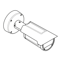
Install the hardware
Attach the metal stand to the camera and use the appropriate screws for the wall/ceiling material.
Note that the camera is designed to be installed with the logotype facing down.
Connect the cables
1. Optionally connect external input/output devices, e.g. alarm devices. See page 12 for informa-
tion on the terminal connector pins.
2. Optionally connect an active speaker and/or external microphone.
3. Connect the camera to the network using a shielded network cable.
4. Connect power, using one of the methods listed below:
• PoE (Power over Ethernet, Class 3). If available, this is automatically detected when the
network cable is connected.
• Connect an external power adapter to the power connector block, see Unit connectors, on
page 12 for wiring information.
5. Check that the indicator LEDs indicate the correct conditions. See the table on page 14 for
further details.
Composite video out (optional)
For quick and easy installation, follow these instructions to view the video signal in a connected
video monitor.
1. Follow the instructions in Connect the cables, on page 5.
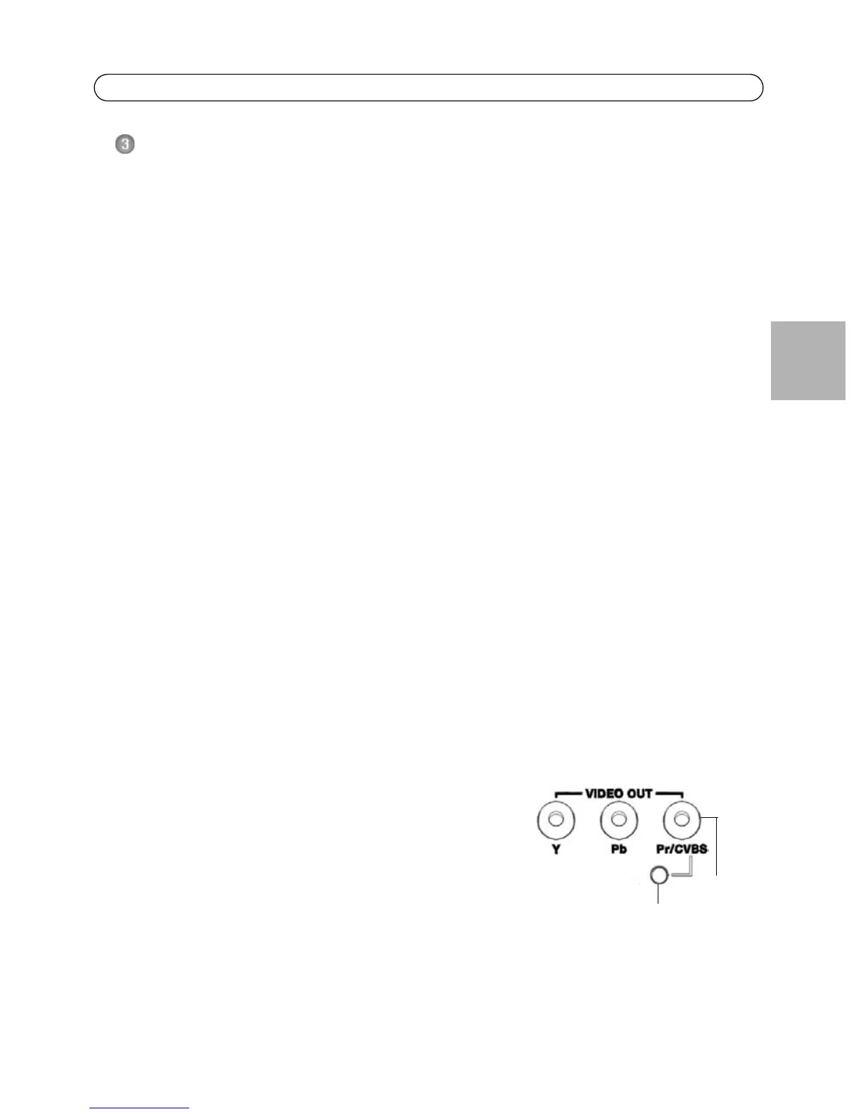
2. Using a composite video cable, connect a video monitor to the Video out Pr/CVBS connector
(red) on the AXIS Q1755.
3. Press and hold the CVBS button for 5 seconds to switch to composite video out (installation
mode).
Note: AXIS Q1755 will stay in installation mode for two (2) minutes and then automatically
revert to Component video. If additional time is required, press the button again.
4. Position the camera and check that the intended area is in
view on the screen.
5. Disconnect the video monitor.
Component video out (optional)
Follow these instructions to view the video signal directly in a
connected HDTV video monitor.
1. Follow the instructions in Connect the cables, on page 5.
2. Connect AXIS Q1755 directly to an HDTV monitor using a component video cable connected to
the Video Out Y/Pb/Pr connectors.
Once the cables have been connected, proceed to Assign an IP address, on page 6.
CVBS button
CVBS
connector
(2 min.)