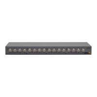
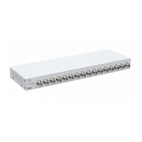
AXISQ7436VideoEncoderBlade
HardwareOverview
PinAssignmentsfortheI/OConnectoroftheAXIS2911UVideoServerRack
PinFunctionDescription
1
+12Vout,100mA
2
GND
3
Channel1,CongurableI/O1
4
Channel2,CongurableI/O1
5
Channel3,CongurableI/O1
6
Channel4,CongurableI/O1
7
Channel5,CongurableI/O1
8
Channel6,CongurableI/O1
9
Channel1,CongurableI/O2
10
Channel2,CongurableI/O2
Digitalinput-ConnecttoGNDtoactivate,
orleaveoating(orunconnected)to
deactivate.
Digitaloutput-UsesanopendrainNFET
transistorwiththesourceconnectedto
GND.Ifusedwithanexternalrelay,adiode
mustbeconnectedinparallelwiththeload,
forprotectionagainstvoltagetransients.
Mininput=–40VDC
Maxinput=+40VDC
Maxload=100mA
Maxvoltage=+40VDC
(tothetransistor)
11
RS485A
12
RS485B
Ahalf-duplexRS485interfaceforcontrollingauxiliaryequipmentsuchasPTZ
devices.
PinassignmentsfortheI/OConnectoroftheAXISQ7920Chassis
PinFunctionDescription
1
Channel1,CongurableI/O1
2
Channel2,CongurableI/O1
3
Channel3,CongurableI/O1
4
Channel4,CongurableI/O1
5
Channel5,CongurableI/O1
6
Channel6,CongurableI/O1
7
Channel1,CongurableI/O2
8
Channel2,CongurableI/O2
9
Channel3,CongurableI/O2
10
Channel4,CongurableI/O2
11
Channel5,CongurableI/O2
12
Channel6,CongurableI/O2
Digitalinput-ConnecttoGNDtoactivate,
orleaveoating(orunconnected)to
deactivate.
Digitaloutput-UsesanopendrainNFET
transistorwiththesourceconnectedto
GND.Ifusedwithanexternalrelay,adiode
mustbeconnectedinparallelwiththeload,
forprotectionagainstvoltagetransients.
Mininput=–40VDC
Maxinput=+40VDC
Maxload=100mA
Maxvoltage=+40VDC
(tothetransistor)
7