15
Chapter 2. Installation, Wiring
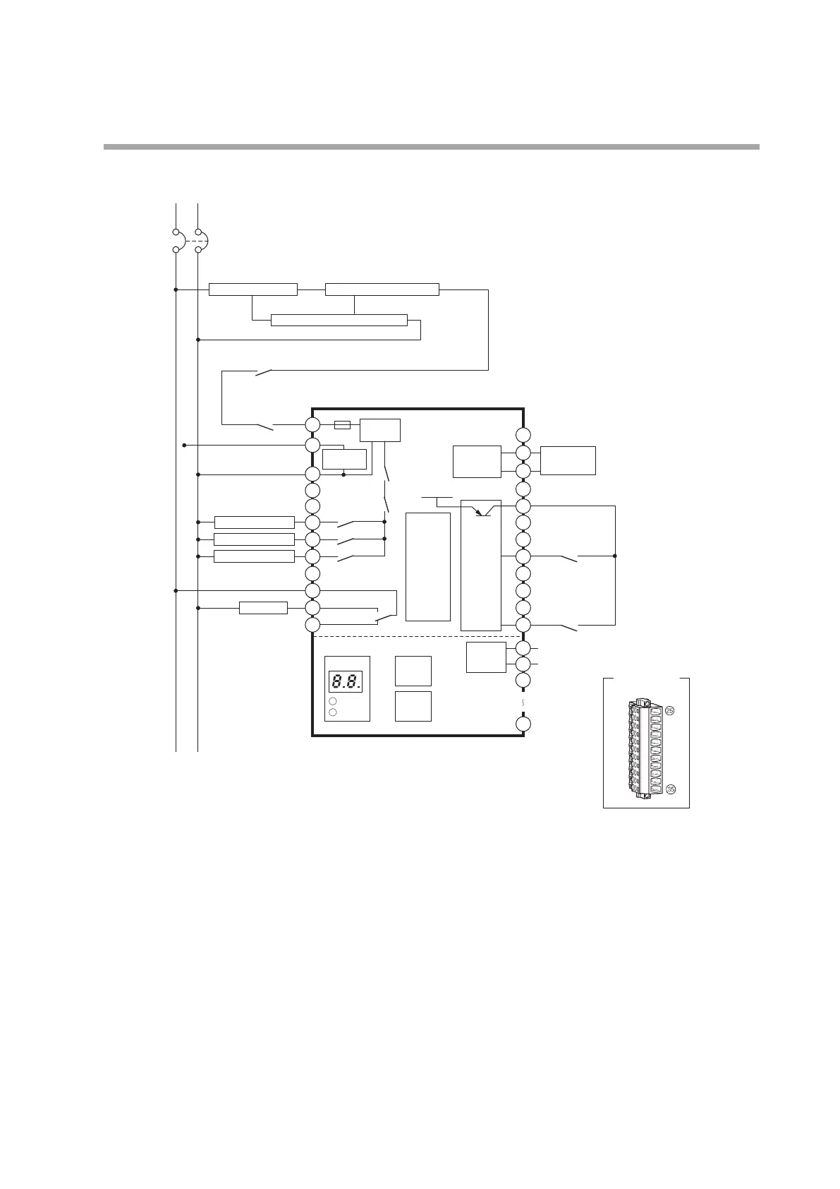
Non-recycling oil-fired combustion (2-level combustion)
Contact reset
Terminal layout
of connector
for front wiring
*1 Use the external controller for either the power or for low voltage.
If the line voltage controller is used to start burner controller operation,
connect terminal 17 to terminal 20.
*2 The contact reset input (terminal 24) must be used by a single AUR890
unit only. Do not use it as the contact reset input of other AUR890 units.
G
F
+
K3
L2(N)
Circuit breaker
Prepurge completion signal
Line voltage
temp. controller
*1
Low voltage
temp. controller
*1
L1
Fuel oil valve
Two-level fuel oil valve
K4
NC
NC
NC
Alarm output COM
NC
NC
NC
NC
NC
NC
NC
NC
NC
Alarm output NO
Alarm output NC
Combustion
safety
control
circuit
RESET
switch
DISP
switch
Power
supply circuit
10A
AUR890/BC-R05A100
Flame
detector
Flame
detection
circuit
AC input
circuit
K2
K1
K6
Ignition transformer
K5
Input
circuit
(24 V DC)
24 V DC
FLAME
ALARM
FV+
FV-
0 to 5 V DC
Flame
voltage
circuit
1
3
5
7
8
2
11
12
9
10
6
4
19
20
23
24
21
22
18
35
25
26
27
13
15
14
16
17
Display
Burner on-off circuit Limit / interlock circuit
Blower operation circuit / prepurge circuit
Alarm
*2

 Loading...


