Chapter 3. Operation
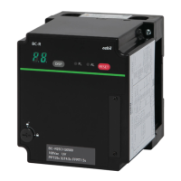
Part names
When a lockout occurs, a alarm code is displayed automatically.
When an alarm occurs, the sequence code and alarm code issued when the lockout
occurred are displayed alternately.
z ID display
Item Notation
• Product number Model AUR890_ _ _ _
• Voltage _ _ _ V AC
• Flame detector (ultraviolet sensor) UV
(Flame rod) Ionization
• Timing display Ignition trial IGT _ _ s
Flame failure response time FFRT _ _ s
Note: “_” represents a number.
Operation
z Reset switch
Lockout is canceled when the reset switch is pressed and held for 1 s.
Note: After the lockout is canceled, a stabilization time of approximately 5 seconds
should be maintained.
During the stabilization time, no start input can be accepted.
z Contact reset input (terminal 24)
Lockout is canceled by connecting the contact reset input (terminal 24) and the
input common (terminal 16 or 17) for 1 second.
Note: After the lockout is canceled, start input is not accepted for approximately 5 seconds.
z DISP switch
z
During normal operation
The 7-segment display shows a sequence code.
Every time the DISP switch is pressed, the display is changed between the sequence
code and flame voltage alternately.
• Sequence codes
Code Description
P
1
Start check
P3
Ignition standby
P4
Lockout timing
P5
Main burner combustion standby
P8
RUN
−− Stop
RESET switch
Switch to cancel lockout
(Press and hold for approximately 1s)
Retaining screw for AUR890 main unit
7-segment LED (green)
When normal: Sequence code/Flame voltage
When an error occurs: Alarm code/Flame voltage
DISP switch
Switch to change as follows:
Flame voltage/Sequence code or
Flame voltage/Alarm code
Flame LED (green)
On during flame signal is detected.
Off when flame signal is not detected.
ID display
Front connector
Flame voltage output (0–5 V)
Loader jack *
* Not used
(for adjustment before shipment)
Retaining screw for AUR890 main unit
ALARM LED (red)
Lit during lockout.
Off when there is no lockout.
21

 Loading...