EasyManuals Logo

Azbil AUR890 Series User Manual

Azbil AUR890 Series
62 pages
To Next Page IconTo Next Page
To Previous Page IconTo Previous Page
Page #17 background imageLoading...
Page #17 background image
9
Chapter 2. Installation, Wiring
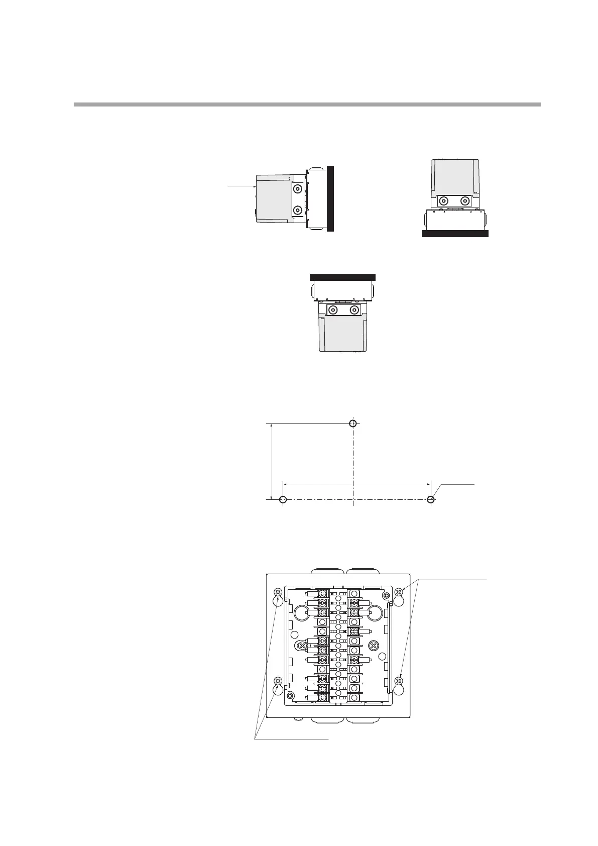
When the base unit (Q890A100) for model RA890 replacement is used
z Installation orientation
Attach the device in the orientation shown below.
Do not install it in the orientations illustrated below.
z Mounting in a panel
(1) Cut three 5 mm diameter holes in the panel.
(Unit: mm)
(2) Loosen the four retaining screws to remove the upper part of the replacement
base unit.
Display area
AUR890
main unit
AUR890
main unit
Correct Correct
AUR890
main unit
Incorrect
104.8
73
(3 locations)
Screws securing the upper part
of the replacement base unit
Screws securing the upper part
of the replacement base unit

Questions and Answers:

Question and Answer IconNeed help?

Do you have a question about the Azbil AUR890 Series and is the answer not in the manual?

Azbil AUR890 Series Specifications

General IconGeneral
Control MethodPID control, fuzzy control
Input TypeThermocouple, RTD, DC voltage, DC current
Output TypeRelay, voltage pulse, current
Control OutputRelay, voltage pulse, current
Output SignalsRelay, voltage pulse, current
Power Supply100 to 240 V AC, 50/60 Hz
DisplayLED
Alarm OutputRelay
CommunicationRS-485
Ambient Temperature0 to 50°C
TypeDigital controller

Related product manuals