26
Chapter 4. Explanation of Operation
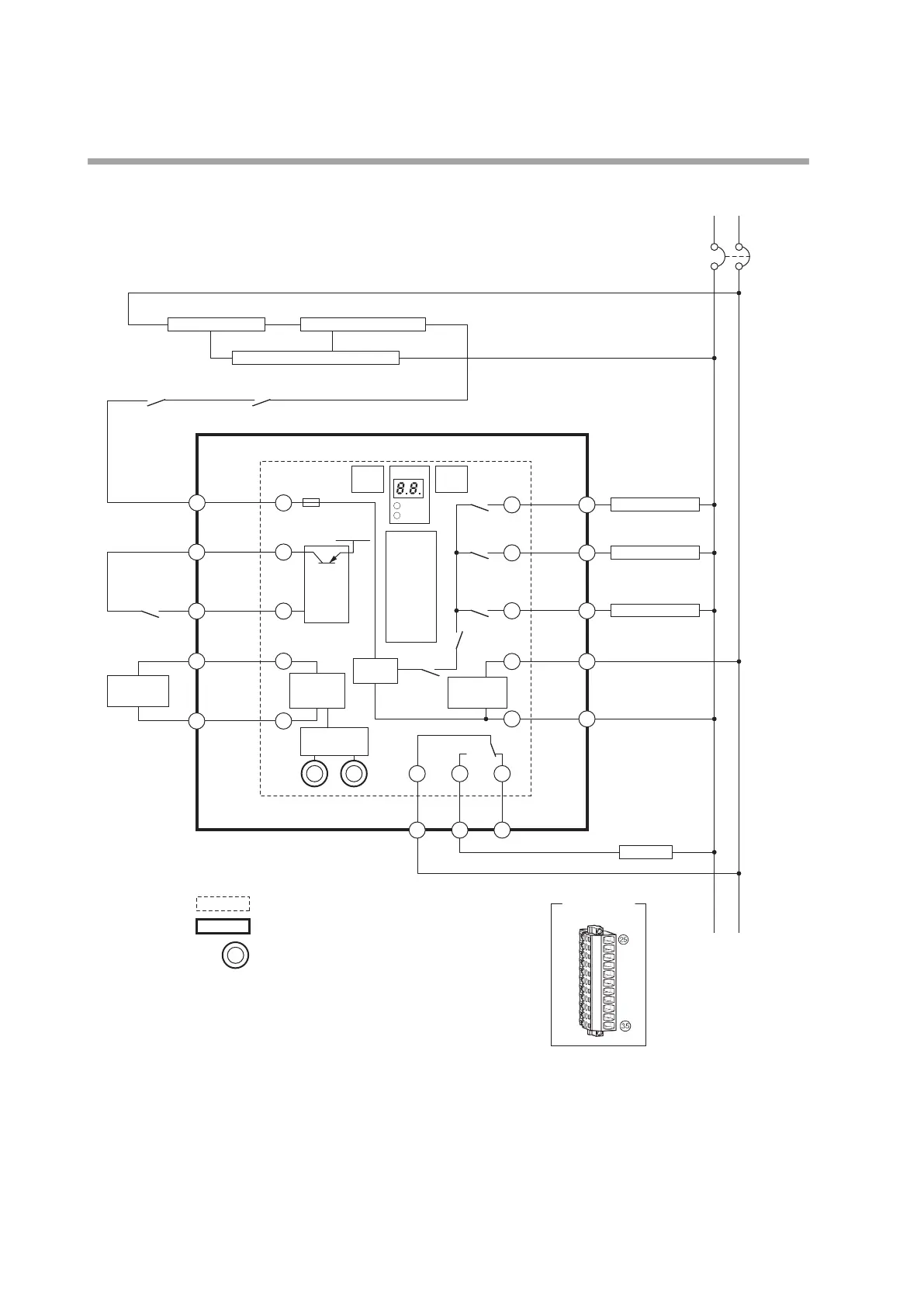
Non-recycling oil-fired combustion (2-level combustion)
Terminal layout
of connector
for front wiring
*1 Use the external controller for either the power
or for low voltage. If the line voltage controller
is used to start burner controller operation,
connect terminal 17 to terminal 20.
: Terminal numbers of AUR890/BC-R05
F
Low voltage
temp. controller
*1
Flame voltage
circuit
10A
Terminal numbers of Q890A100 base unit (for RA890 replacement)
AUR890/BC-R05A100
5
L1
Circuit
breaker
L2(N)
Line voltage
temp. controller
*1
Prepurge completion signal
1
Burner on-off circuit Limit / interlock circuit
Blower operation circuit / prepurge circuit
AC input
circuit
6
Fuel oil valve
Two-level fuel oil valve
Ignition transformer
8
46
37
12
23
10
25
RESET
switch
DISP
switch
FLAME
ALARM
Display
Combustion
safety
control
circuit
Input
circuit
(24 V DC)
24 V DC
17
T
+
20
T
14
F
G
FV+ FV
-
Alarm
output
COM
15
G
Flame
detector
Flame
detection
circuit
K1
Power
supply circuit
K4
K5
K3
K2
K6
26
: Terminal numbers of Q890A100 base unit
(for RA890 replacement)
: Terminal numbers of the front connector
Alarm
COM
11
Alarm
output
NO
NO
12
Alarm
output
NC
NC

 Loading...


