1
CP-SP-1213E
Quick Reference Guide for Model C15
This guide offers a summary of key operations, parameter flowcharts, and settings, for convenient reference at
the operation site. This guide is made for repeated use. Dirt wipes off easily and even notes written with an oil-
based felt-tip pen can be removed with an eraser. If more detailed information on model C15 is needed, refer
to the user's manuals: CP-SP-1147E for basic operation and CP-SP-1148E for installation and configuration.
The most convenient way to configure the C15 is with the Smart Loader Package (model No. SLP-C35J50).
Please contact the azbil Group or a distributor for more information.
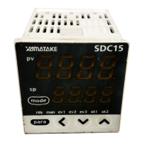
Upper display
Indicators during AT
[para] key
Mode indicators
Lower display
Various indicators
Loader connector (bottom panel)
[mode] key
[ ], [ ], and [ ] keys
Upper display This display shows either the PV value or the display value and set value for each displayed item. If an alarm is triggered, the
normal display and alarm code are displayed alternately. During auto tuning (AT), the rightmost decimal point flashes twice
repeatedly.
Lower display This display shows either the SP/MV/CT or the display value and set value for each displayed item. The rightmost decimal
point lights up or flashes to show RUN/READY mode or communications status, depending on the setting.
Mode indicators rdy: Lights when READY (RUN mode if not lit)
man: Lights when MANUAL (AUTO mode if not lit)
ev1, ev2, ev3: Lights when event relays are ON
ot1, ot2: Lights when the control output is ON (always lit when the current output is used)
[mode] key
• When this key is pressed and held for more than 1 second in the operation display mode, any of the following operations
from 0 to 7 which have been set previously can be executed:
0 : Mode key does not operate (Initial value)
1 : AUTO/MANUAL mode selection
2 : RUN/READY mode selection
3 : AT (Auto Tuning) start/stop selection
4 : LSP (Local SP) group selection
5 : Release all DO (Digital Output) latches
6 : Mode key does not operate
7 : ON/OFF selection of communication DI1
• When pressing the [mode] key in the setup display mode, the display is changed to the operation display
[para] key
• This key is used to change the display item.
• When this key is kept pressed for 2 s. or longer in the operation display mode, the display is then changed to the setup
display
[<], [
] , [ ] keys
Theses keys are used to increase or decrease the numeric value, or to shift the digit.
Loader connector The Smart Loader connector is on the bottom of the C15. Use the dedicated cable that is included with the Smart Loader
Package to connect the controller to a PC.
: Initial value
(Not for use in Japan)

 Loading...