6
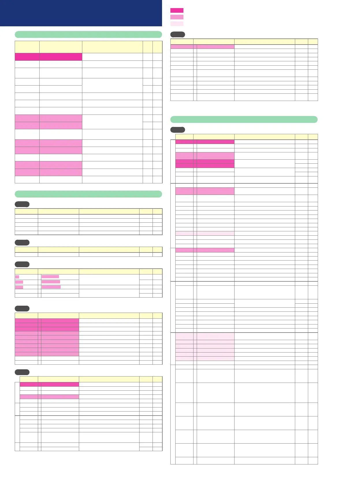
List of operation displays
Display
Upper display: PV
Lower display: SP
Item Contents Initial
value
Setting
value
PV
SP
SP (Target value) SP low limit to SP high limit 0
LSP
1
(
Display example
)
LSP
LSP No.
(
1st digit: Value at the right end digit
)
1 to LSP system group (Max. 4) 1
Out
MV
MV (Manipulated Variable) -10.0 to +110.0%
Setting is enabled in MANUAL mode
(Numeric value flashed)
HEAt
Numeric value
Heat MV (Manipulated Variable) Setting is disabled.
-10.0 to +110.0%
COOL
Numeric value
Cool MV (Manipulated Variable)
PV
At
1
(
Display example
)
AT progress display
(
1st digit=Numeric value at right end digit
)
Setting is disabled.
Ct
1
Numeric value
CT current value 1 Setting is disabled.
Ct2
Numeric value
CT current value 2 Setting is disabled.
E
1
Numeric value
Internal Event 1 main setting -1999 to +9999U or 0 to 9999U 0
E
1.Sb
Numeric value
Internal Event 1 sub setting 0
t
1.--
(
Display example
)
Numeric value
Timer remaining time 1 Setting is disabled.
Upper display: The distinction by ON delay or
OFF delay is displayed at the side location of “t1.”.
E2
Numeric value
Internal Event 2 main setting Same as Internal Event 1 main setting 0
E2.Sb
Numeric value
Internal Event 2 sub setting Same as Internal Event 1 sub setting 0
t2.--
(
Display example
)
Numeric value
Timer remaining time 2 Same as Timer remaining time 1
E3
Numeric value
Internal Event 3 main setting Same as Internal Event 1 main setting 0
E3.Sb
Numeric value
Internal Event 3 sub setting Same as Internal Event 1 sub setting 0
t3.--
(
Display example
)
Numeric value
Timer remaining time 3 Same as Timer remaining time 1
List of parameter setting displays
MOdE
[Mode bank]
Display Item Contents
Initial value
Setting value
A--M
AUTO/MANUAL
AUTO
: AUTO mode
MAN
: MANUAL mode
AUTO
r--r
RUN/READY
RUN
: RUN mode
RDY
: READY mode
RUN
At
AT stop/start
At.OF
: AT stop
At.ON
: AT start
AT stop
dO.Lt
Release all DO latches
Lt.ON
: Latch continue
Lt.OF
: Latch release
Latch continue
C.dI
1
Communication DI1
dI
.OF
: OFF
dI
.On
: ON
OFF
SP
[SP bank]
Display Item Contents
Initial value
Setting value
SP-
1
to
SP-4
SP (for LSP1 to 4) SP low limit to SP high limit 0
Ev
[Event bank]
Display Item Contents
Initial value
Setting value
E
1
to
E5
Internal Event 1 to 5 main setting
-1999 to +9999 or 0 to 9999 * 0
E
1.Sb
to
E5.Sb
Internal Event 1 to 5 sub setting
0
E
1.Hy
to
E5.Hy
Internal Event 1 to 5 hysteresis
0 to 9999 * 5
E
1.On
to
E5.On
Internal Event 1 to 5 ON delay time
0.0 to 999.9 or 0 to 9999 0
E
1.OF
to
E5.OF
Internal Event 1 to 5 OFF delay time
0
* The decimal point position varies by meeting the internal event operation type.
PI
D
[PID bank]
Display Item Contents
Initial value
Setting value
P-
1
Proportional band (PID1) 0.1 to 999.9% 5.0
I
-
1
Integration time (PID1) 0 to 9999s (
No integration control action when set at "0"
) 120
d-
1
Derivative time (PID1) 0 to 9999s (
No derivative control action when set at "0"
) 30
rE-
1
Manual reset (PID1) -10.0 to +110.0% 50.0
OL-
1
MV low limit (PID1) -10.0 to +110.0% 0.0
OH-
1
MV high limit (PID1) -10.0 to +110.0% 100.0
P-
1C
Cool-side proportional band
(PID1) 0.1 to 999.9% 5.0
I
-
1C
Cool-side integration time
(PID1) 0 to 9999s (
No integration control action when set at "0"
) 120
d-
1C
Cool-side derivative time
(PID1) 0 to 9999s (
No derivative control action when set at "0"
) 30
OL.
1C
Cool-side MV low limit (PID1) -10.0 to +110.0% 0.0
OH.
1C
Cool-side MV high limit (PID1) -10.0 to +110.0% 100.0
PARA
[Parameter bank]
Display Item Contents
Initial value
Setting value
Control
CtrL
Control method 0: ON/OFF control 1: Fixed PID 2: ST(Self-tuning) 0 or 1
At.
OL
MV low limit at AT -10.0 to +110.0% 0.0
At.
OH
MV high limit at AT -10.0 to +110.0% 100.0
dI
FF
ON/OFF control differential 0 to 9999U 5
OFFS
ON/OFF control operating point offset
-1999 to +9999U 0
PV
FL
PV filter 0.0 to 120.0s 0.0
rA
PV ratio 0.001 to 9.999 1.000
bI
PV bias -1999 to +9999U 0
Time proportional output
CyU
Time proportional cycle unit 1 0 to 3 *
1
0
Cy
Time proportional cycle 1 5 to 120s or 1 to 120s *
2
10 or 2
CyU2
Time proportional cycle unit 2 0 to 3 *
1
0
Cy2
Time proportional cycle 2 5 to 120s or 1 to 120s *
2
10 or 2
tP.
ty
Time proportional cycle mode
0: Controllability aiming type
1:
Operation end service life aiming type (Only ON/
OFF operation within Time proportional cycle)
0 or 1
SP
SPU
SP up ramp (U/min) 0.0 to 999.9U(No ramp when set at "0.0U") 0.0
SPd
SP down ramp (U/min) 0.0
*1 0: Unit of "1s" 1: Fixed at 0.5s 2: Fixed at 0.2s 3: Fixed at 0.1s
*2 5 to 120s when output includes the relay output
U: Unit Maximum unit of Industrial volume in
PV range (°C, Pa,L/min, etc.)
: Essential parameters for PV measurement and control
: Basic parameters
: Required parameters when using optional functions
Et
[Extended tuning bank]
Display Item Contents
Initial value
Setting value
At.ty
AT type 0: Normal 1: Immediate response 2: Stable *
1
1
JF.bd
Just-FiTTER setting band 0.00 to 10.00 0.30
SP.LG
SP lag constant 0.0 to 999.9 0.0
At-P
AT Proportional Band adjust 0.00 to 99.99 1.00
At-I
AT Integral time adjust 0.00 to 99.99 1.00
At-d
AT Derivative time adjust 0.00 to 99.99 1.00
Ctr.A
Control algorithm 0: PID(Conventional PID)
1: Ra-PID(High-performance PID)
0
JF.Ov
Just-FiTTER assistance coefficient
0 to 100 0
St.SA
ST step execution resolution band
0.0 to 99.99 10.0
St.Sb
ST step setting band 0.0 to 10.00 0.50
St.Hb
ST hunting setting band 0.0 to 10.00 1.00
St.ud
ST step ramp change 0: ST is executed when the PV moves up or down.
1: ST is executed only when the PV moves up.
0
*1 Normal = Standard control characteristics, Immediate response = Control characteristics that respond immediately to
external disturbance, Stable = Control characteristics having less up/down fluctuation of PV
List of setup setting displays
StUP
[Setup bank]
Display Item Contents
Initial value
Setting value
Analog input
C0
1
PV input range type For details, refer to the PV Input Range Table
Depending on Model No.
C02
Temperature unit 0: Celsius (°C) 1: Fahrenheit (°F) 0
C03
Cold junction compensation
0: Performed (internal) 1: Not performed (external)
0
C04
Decimal point position 0: No decimal point
1 to 3: 1 to 3 digits below decimal point *
1
0
C05
PV range low limit
When the PV input type is DC voltage/DC current,
-1999 to +9999U
0
C06
PV range high limit 1000
C07
SP low limit PV input range low limit to PV input range high
limit
C08
SP high limit
C09
PV square root extraction dropout
0.0 to 100.0% (PV square root extraction is not
performed when set at "0.0".)
0.0
Control action
C
13
PID calculation adjustment function
*
2
0: Enabled 1: Disabled 0
C
14
Control action (Direct/Reverse)
0: Heat control (Reverse action)
1: Cool control (Direct action)
0
C
15
Output operation at PV alarm 0: Control calculation is continued.
1: Output at PV alarm is output.
0
C
16
Output at PV alarm -10.0 to +110.0% 0.0
C
17
Output at READY (Heat) -10.0 to +110.0% 0.0
C
18
Output at READY (Cool) -10.0 to +110.0% 0.0
C
19
Output operation at changing AUTO/MANUAL
0: Bumpless transfer 1: Preset 0
C20
Preset MANUAL value -10.0 to +110.0%
0.0 or 50.0
C2
1
Initial output type (mode) of PID control
0: Auto 1: Not initialized 2: Initialized 0
C22
Initial output of PID control -10.0 to +110.0%
0.0 or 50.0
C26
Heat/Cool control 0: Not used 1: Used 0
C27
Heat/Cool 0: Normal 1: Energy saving 0
C28
Heat/Cool control dead zone -100.0 to +100.0% 0.0
C29
Heat/Cool change point -10.0 to +110.0% 50.0
SP
C30
LSP system group 1 to 4 1
C32
SP ramp unit 0: 0.1U/s 1: 0.1U/min 2: 0.1U/h 1
C36
CT1 operation type
0: Heater burnout detection 1: Current value measurement
0
C37
CT1 output
0 to 1: Control output 1 to 2, 2 to 4: Event output 1 to 3
0
C38
CT1 measurement wait time 30 to 300ms 30
C39
CT2 operation type Same as CT1 0
C40
CT2 output Same as CT1 0
C4
1
CT2 measurement wait time Same as CT1 30
Continuous output
C42
Control output 1 range 1: 4 to 20mA 2: 0 to 20mA 1
C43
Control output 1 type 0: MV 1: Heat MV 2: Cool MV 3: PV
4: PV before ratio, bias, and filter 5: SP
6: Deviation 7: CT1 current value
8: CT2 current value 10: SP+MV 11: PV+MV
0
C44
Control output 1 scaling low limit
-1999 to +9999U 0.0
C45
Control output 1 scaling high limit
100.0
C46
Control output 1 MV scaling bandwidth
0 to 9999 (Valid when control output 1 type is 10 or 11)
200
C47
Control output 2 range Same as control output 1 1
C48
Control output 2 type Same as control output 1 3
C49
Control output 2 scaling low limit
Same as control output 1 0
C50
Control output 2 scaling high limit
Same as control output 1 1000
C5
1
Control output 2 MV scaling bandwidth
Same as control output 1 200
Communication
C64
Communication type 0: CPL 1: Modbus (ASCII format)
2: Modbus (RTU format)
0
C65
Station address
0 to 127 (Communication is disabled when set at "0".)
0
C66
Transmission speed (bps) 0: 4800 1: 9600 2: 19200 3: 38400 2
C67
Data format (Data length) 0: 7 bits 1: 8 bits 1
C68
Data format (Parity) 0: Even parity 1: Odd parity 2: No parity 0
C69
Data format (Stop bit) 0: 1 bit 1: 2 bits 0
C70
Communication minimum response time
1 to 250ms 3
Key operation • display
C7
1
Key operation type 0: Standard type 1: Special type 0
C72
[mode] key function 0: Invalid 1: AUTO/MANUAL selection
2: RUN/READY selection 3: AT Stop/Start
4: LSP group selection 5: Release all DO latches
6: Invalid 7:
Communication DI1 selection
8:
Invalid
0
C73
MODE display setup
(Sum of the weighting)
Bit 0: AUTO/MANUAL display (Enabled: +1)
Bit 1: RUN/READY display (Enabled: +2)
Bit 3: AT Stop/Start display (Enabled: +8)
Bit 4:
Release all DO latches display (Enabled: +16)
Bit 5:
Communication DI1 ON/OFF display (Enabled: +32)
Other invalid setting, 0, +4, +64, +128
255
C74
PV/SP display setup
(Sum of the weighting)
Bit 0: PV display (Enabled: +1)
Bit 1: SP display (Enabled: +2)
Bit 2: LSP group number display (Enabled: +4)
Other invalid setting, 0, +8
15
C75
MV display setup
(Sum of the weighting)
Bit 0: MV display (Enabled: +1)
Bit 1: Heat MV/cool MV display (Enabled: +2)
Bit 3: AT progress display (Enabled: +8)
Other invalid setting: 0, +4
15
C76
EV display setup
(Operation display)
0: Not displayed
1: Set value of Internal event 1 is displayed
2: Set values of Internal event 1 to 2 are displayed
3: Set values of Internal event 1 to 3 are displayed
0
C77
Event remaining time display setup
(Operation display)
0: Not displayed
1: Internal event 1 is displayed
2: Internal event 1 to 2 is displayed
3: Internal event 1 to 3 is displayed
0
C78
CT input current value display setup
(Operation display)
0: Not displayed 1: CT1 current value is displayed
2: CT1 to 2 current values are displayed
0
List of parameters
 Loading...


