8
1-12-2 Kawana, Fujisawa
Kanagawa 251-8522 Japan
URL
: https://www.azbil.com
(11)
Specifications are subject to change without notice.
PV input range table
[Thermocouple] [RTD]
C0
1
set value
Sensor
type
Range
(°C)
Range
(°F)
C0
1
set value
Sensor
type
Range
(°C)
Range
(°F)
1 K -200 to +1200 -300 to +2200 41 Pt100 -200 to +500 -300 to +900
2 K 0 to 1200 0 to 2200 42 JPt100 -200 to +500 -300 to +900
3 K 0.0 to 800.0 0 to 1500 43 Pt100 -200 to +200 -300 to +400
4 K 0.0 to 600.0 0 to 1100 44 JPt100 -200 to +200 -300 to +400
5 K 0.0 to 400.0 0 to 700 45 Pt100 -100 to +300 -150 to +500
6 K -200.0 to +400.0 -300 to +700 46 JPt100 -100 to +300 -150 to +500
9 J 0.0 to 800.0 0 to 1500 51 Pt100 -50.0 to +200.0 -50 to +400
10 J 0.0 to 600.0 0 to 1100 52 JPt100 -50.0 to +200.0 -50 to +400
11 J -200.0 to +400.0 -300 to +700 53 Pt100 -50.0 to +100.0 -50 to +200
13 E 0.0 to 600.0 0 to 1100 54 JPt100 -50.0 to +100.0 -50 to +200
14 T -200.0 to +400.0 -300 to +700 63 Pt100 0.0 to 200.0 0 to 400
15 R 0 to 1600 0 to 3000 64 JPt100 0.0 to 200.0 0 to 400
16 S 0 to 1600 0 to 3000 67 Pt100 0 to 500 0 to 900
17 B 0 to 1800 0 to 3300 68 JPt100 0 to 500 0 to 900
18 N 0 to 1300 0 to 2300
[DC voltage/DC current]
19 PL II 0 to 1300 0 to 2300
20
WRe5-26
0 to 1400 0 to 2400
C0
1
set value
Input type Range
21
WRe5-26
0 to 2300 0 to 4200
23
PR40-20
0 to 1900 0 to 3400 84 0 to 1 V The scaling and decimal
point position can be
changed variably in a
range of –1999 to +9999
24 DIN U -200.0 to +400.0 -300 to +700 86 1 to 5 V
25 DIN L -100.0 to +800.0 -150 to +1500 87 0 to 5 V
88 0 to 10 V
89 0 to 20 mA
Initial value 90 4 to 20 mA
*1
• Accuracy for No. 17 (B thermocouple) is as follows. 260 °C or less: ±5 %FS. 260–800 °C: ±1 %FS.
The PV values under 20 °C are not shown. However, if ROM version 1 (
i
d02
) of the instrument
information bank is 2.04 or earlier, the indicated low limi value is -180 °C.
• Accuracy for No. 23 (sensor type PR40-20) is as follows. 300 °C or less: undefined. 300–800 °C:
±5 % FS. 800–1900 °C: ±2 % FS. However, if ROM version 1 (
i
d02
) of the instrument information
bank is 2.26 or earlier, No. 23 cannot be selected.
*2 PL II thermocouple is a range, which has been added to the units manufactured from July, 2003.
*3 The decimal point for thermocouples can be displayed if the ROM version is 2.26 or later.
List of alarm codes
Alarm
code
Failure name Cause Corrective action
Input failure
AL0
1
PV input failure
(Over-range)
Sensor burnout, incorrect
wiring, incorrect PV input
type setting
Check the wiring.
Set the PV input type
again.
AL02
PV input failure
(Under-range)
Sensor burnout, incorrect
wiring, incorrect PV input
type setting
AL03
CJ failure Terminal temperature is
faulty (thermocouple).
Check the ambient
temperature.
PV input failure
(RTD)
Sensor burnout, incorrect
wiring
Check the wiring.
AL
1
1
CT input failure
(Over-range)
(CT input 1 or 2,
or both)
A current exceeding the
upper limit of the display
range was measured. The
number of CT turns or the
number of CT power wire
loops is incorrectly set, or
wiring is incorrect.
• Use a CT with the cor-
rect number of turns
for the display range.
• Reset the number of
CT turns.
• Reset the number of CT
power wire loops.
• Check the wiring.
Unit failure
AL70
A/D conversion
failure
A/D converter is faulty. Replace the unit.
AL95
Parameter failure Power is shut-down while
the data is being set, or
data is corrupted by noise.
• Restart the unit.
• Set the data again (set
data for
AL95
/
97
and
adjustment data for
AL96
/
98
.
• Replace the unit.
AL96
Adjustment data
failure
Power is shut-down while
the data is being set, or
data is corrupted by noise.
AL97
Parameter failure
(RAM area)
Data is corrupted by noise.
AL98
Adjustment data
failure (RAM area)
Data is corrupted by noise.
AL99
ROM failure ROM (memory) is faulty. • Reset the unit.
• Replace the unit.
Handling Precautions
• If ROM version 1 (
i
d02
) of the instrument information bank is
2.04 or earlier, CT input failure (
AL
1
1
) is not displayed.
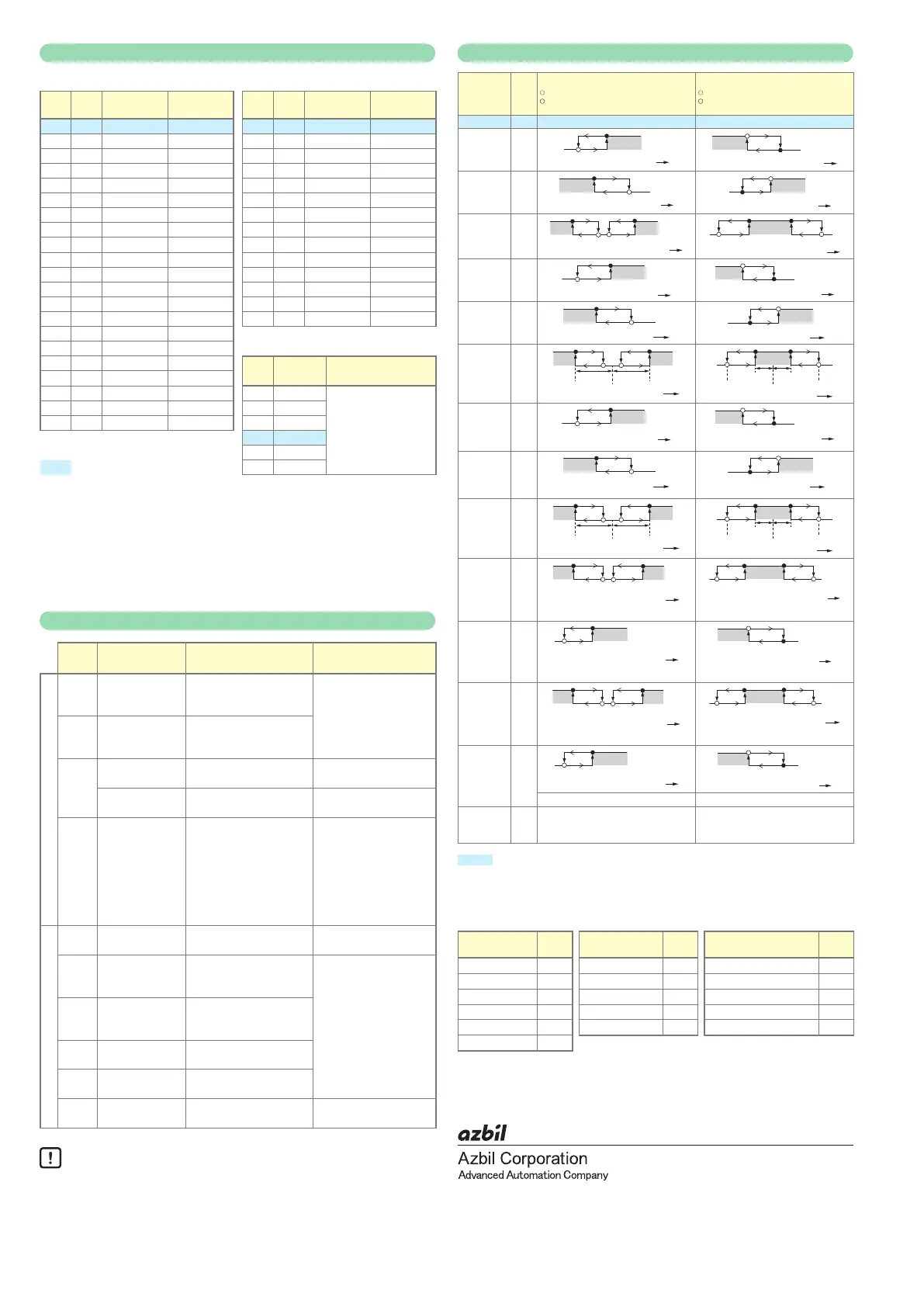
Event type
Operation
type
Set
value
Direct action
:
shows that the ON/OFF is changed at this value.
:
shows that the ON/OFF is changed at a point
that "1U" is added to this value.
Reverse action
:
shows that the ON/OFF is changed at this value.
:
shows that the ON/OFF is changed at a point
that "1U" is added to this value.
No event 0 Always OFF Always OFF
PV high
limit
1
ONHYS
Main setting
ON
HYS
Main setting
PV low limit 2
Main setting
ON
HYS
ON
HYS
PV high/low
limit
3
*
Sub-setting
*
ON HYS ONHYS
Main setting
*
Sub-setting
*
ONHYS
HYS
Deviation
high limit
4
ONHYS
SP + Main setting
ON
HYS
SP + Main setting
Deviation
low limit
5
ON HYS
ONHYS
Deviation
high/low
limit
6
Main setting Sub-setting
SP
ON HYS
ONHYS
ONHYS HYS
Main setting
Sub-setting
SP
Deviation
high limit
(Final SP
reference)
7
ONHYS
SP + Main setting
ON
HYS
SP + Main setting
Deviation
low limit
(Final SP
reference)
8
ON HYS
ONHYS
Deviation
high/
low limit
(Final SP
reference)
9
Main setting Sub-setting
SP
ON HYS
ONHYS
ONHYS HYS
Main setting
Sub-setting
SP
Heater 1
burnout/
Over-current
16
CT1 at output ON
Main setting
*
Sub-setting
*
ON HYS
ONHYS
ONHYS HYS
Main setting
*
Sub-setting
*
OFF before measuring the CT1 current value
OFF before measuring CT1 current value
Heater 1
short-circuit
17
ON
HYS
Main setting
ON
HYS
Main setting
OFF before measuring CT1 current value OFF before measuring CT1 current value
Heater 2
burnout/
Over-current
18
Main setitng
*
Sub-setting
*
ON HYS
ONHYS
ONHYS HYS
Main setting
*
Sub-setting
*
OFF before measuring CT2 current value OFF before measuirng CT2 current value
Heater 2
short-circuit
19
ON
HYS
Main setting
ON
HYS
Main setting
OFF before measuring CT2 current value OFF before measuring CT2 current value
Alarm
(status)
23 ON if alarm occurs (alarm code AL01
to 99).
OFF in other cases.
OFF if alarm occurs (alarm code AL01
to 99).
ON in other cases.
: initial value
*: If the main setting is greater than the sub-setting, operations are performed with the
main setting and sub-setting automatically swapped.
Event types other than the above:
Operation type Set
value
Operation type Set
value
Operation type Set
value
SP high limit 10 Loop diagnosis 1 20 During AT (status) 27
SP low limit 11 Loop diagnosis 2 21 During SP ramp 28
SP high/low limit 12 Loop diagnosis 3 22 Control action (status) 29
MV high limit 13 READY (status) 24 ST setting standby (status) 30
MV low limit 14 MANUAL (status) 25 Timer (status) 32
MV high/low limit 15
1st edition: Mar. 2007 (W)
3rd edition: Apr. 2019 (B) © 2007–2019 Azbil Corporation. All Rights Reserved.
 Loading...


