E8
(10)
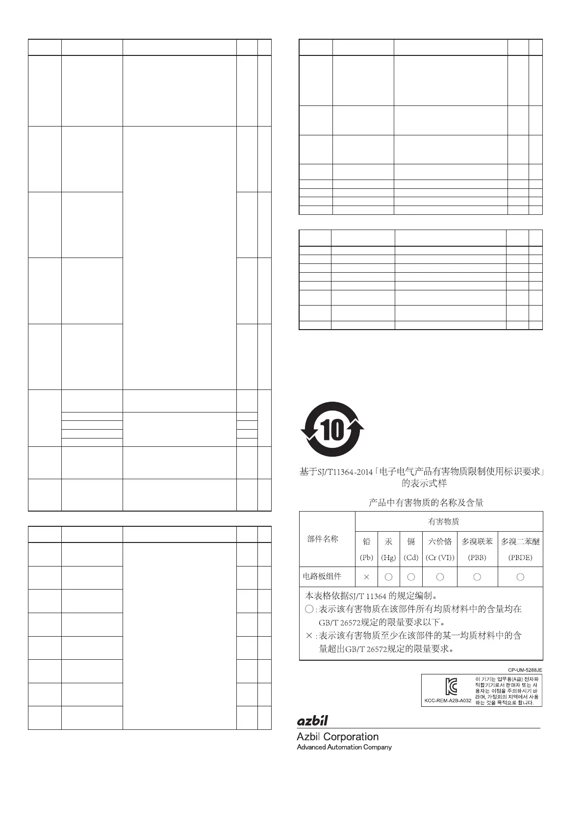
1-12-2 Kawana, Fujisawa
Kanagawa 251-8522 Japan
URL
: https://www.azbil.com
Specications are subject to change without notice.
1st edition: Sep. 2003
23rd edition: Oct. 2018 (V)
Do assignment bank: dO
Display Item Contents Initial
value
User
level
Ot 1. 1 to
Ot2. 1
Ev 1. 1 to
Ev3. 1
Control output 1 to 2,
event output 1 to 3
Oper
ation type
0: Input of default
1: MV1 (ON/OFF control output, time
proportional output, heat-side proportional
output of heat/cool control)
2: MV2 (cool-side proportional output of heat/
cool control)
3: Function 1 ((A and B) or (C and D))
4: Function 2 ((A or B) and (C or D))
5: Function 3 (A or B or C or D)
6: Function 4 (A and B and C and D)
0 2
Ot 1.2 to
Ot2.2
Ev 1.2 to
Ev3.2
Control output 1 to 2,
event output 1 to 3
O
utput assignment A
0: Normally open (OFF, 0)
1: Normally close (ON, 1)
2: Internal event 1
3: Internal event 2
4: Internal event 3
5: Internal event 4
6: Internal event 5
7 to 13: Undefined
14: MV1
15: MV2
16, 17: Undefined
18: DI1
19: DI2
20: DI3
21: DI4
22 to 25: Undefined
26: Internal contact 1
27: Internal contact 2
28: Internal contact 3
29: Internal contact 4
30: Internal contact 5
31 to 33: Undefined
34: Communication DI1
35: Communication DI2
36: Communication DI3
37: Communication DI4
38: MANUAL mode
39: READY mode
40: Undefined
41: During AT execution
42: During SP ramp
43: Undefined
44: Alarm is enabled.
45: PV alarm is enabled.
46: Undefined
47: Mode key function selection status
48: Event output 1 status
49: Control output 1 status
14, 15
or
2 to 4
2
Ot
1.3 to
Ot2.3
Ev 1.3 to
Ev3.3
Control output 1 to 2,
event output 1 to 3
O
utput assignment B
0 2
Ot 1.4 to
Ot2.4
Ev 1.4 to
Ev3.4
Control output 1 to 2,
event output 1 to 3
O
utput assignment C
0 2
Ot 1.5 to
Ot2.5
Ev 1.5 to
Ev3.5
Control output 1 to 2,
event output 1 to 3
O
utput assignment D
0 2
Ot 1.6 to
Ot2.6
Ev 1.6 to
Ev3.6
Control output 1 to 2,
event output 1 to 3
P
olarity A to D
Digits are called as 1st digit, 2nd digit, 3rd digit
and 4th digit from the right end digit.
0000 2
1st digit: Polarity A 0: Direct
1: Reverse
0
2nd digit: Polarity B 0
3rd digit: Polarity C 0
4th digit: Polarity D 0
Ot 1.7 to
Ot2.7
Ev 1.7 to
Ev3.7
Control output 1 to 2,
event output 1 to 3
P
olarity
0: Direct
1: Reverse
0 2
Ot 1.8 to
Ot2.8
Ev 1.8 to
Ev3.8
Control output 1 to 2,
event output 1 to 3 Latch
0: Disabled
1: Enabled (La
tch at ON)
2: Enabled (Latch at OFF, except at the time of
initialization after power ON)
0 2
User function bank: UF
Display Item Contents Initial
value
User
level
UF- 1
User function
definition1
This is the display in upper display. The setup
exception is as follows:
----: Yet to be registered.
P-_ : Proportional band of the PID group in
use
I -_ : Integration time of the PID group in
use
d-_ : Derivative time of the PID group in
use
rE-_ : Manual reset of the PID group in use
OL-_ : MV low limit of the PID group in use
OH-_ : MV high limit of the PID group in use
P-_ C: Cool-side proportional band of the
PID group in use
I -_ C: Cool-side integration time of the PID
group in use
d-_ C: Cool-side derivative time of the PID
group in use
Ol._ C: Cool-side MV low limit of the PID
group in use
Oh._ C: Cool-side of MV high limit of the PID
group in use
- - - - 1
UF-2
User function
definition2
- - - - 1
UF-3
User function
definition3
- - - - 1
UF-4
User function
definition4
- - - - 1
UF-5
User function
definition5
- - - - 1
UF-6
User function
definition6
- - - - 1
UF-7
User function
definition7
- - - - 1
UF-8
User function
definition8
- - - - 1
Lock bank: LOC
Display Item Contents Initial
value
User
level
LOC
Key lock 0: All settings are enabled.
1: Mode, event, operation display, SP, UF, lock,
manual MV, and mode key can be set.
2: Operation display, SP, UF, lock, manual MV,
and mode key can be set.
3: UF, lock, manual MV, and mode key can
be set.
0 0
C.LOC
Communication lock 0: RS-485 communication read/write is
enabled.
1: RS-485 communication read/write is
disabled.
0 2
L.LOC
Loader lock 0: Loader communication read/write is
enabled.
1: Loader communication read/write is
disabled.
0 2
PASS
Password display 0 to 15
5: Password 1A to 2B display
0 0
PS 1A
Password 1A 0000 to FFFF (hexadecimal value) 0000 0
PS2A
Password 2A 0000 to FFFF (hexadecimal value) 0000 0
PS 1b
Password 1B 0000 to FFFF (hexadecimal value) 0000 0
PS2b
Password 2B 0000 to FFFF (hexadecimal value) 0000 0
Instrument information bank: I d
Display Item Contents Initial
value
User
level
I d0 1
ROM ID 1 fixed — 2
I d02
ROM version 1 XX. XX (2 digits after decimal point) — 2
I d03
ROM version 2 XX. XX (2 digits after decimal point) — 2
I d04
SLP support Information — 2
I d05
EST support version — 2
I d06
Manufacturing date code
(year)
Year −2000
Ex.: “3” means the year 2003.
— 2
I d07
Manufacturing date code
(month, day)
Month + Day ÷ 100
Ex.: “12.01” means the 1st day of December
— 2
I d08
Serial No. — 2