E1
CP-UM-5288JE (Not for use in Japan)
SDC25/26
Single Loop Controller
User’s Manual for Installation
Thank you for purchasing an Azbil Corporation product.
Before operating this product described in this User’s Manual,
please take note of the following points regarding safety.
Be sure to keep this manual nearby for handy reference.
Please read “Terms and Conditions” from the following URL be-
fore ordering and use.
https://www.azbil.com/products/factory/order.html
NOTICE
Be sure that the user receives this manual before the product is used.
Copying or duplicating this user’s manual in part or in whole is for-
bidden. The information and specifications in this manual are sub-
ject to change without notice.
Considerable effort has been made to ensure that this manual is free
from inaccuracies and omissions. If you should find an error or omis-
sion, please contact the azbil Group.
In no event is Azbil Corporation liable to anyone for any indirect,
special or consequential damages as a result of using this product.
© 2003–2018 Azbil Corporation. All Rights Reserved.
This manual explains the handling precautions, mounting, wiring,
PVrange type, list of parameters and main specifications only. See the
separate “Installation & Configurations” manual listed below for the detail
handling procedures and the setting methods, etc. These manuals also
contain information on using various functions. Please read if necessary.
SDC25/26 Single Loop Controller User’s Manual for Installation &
Configuration CP-SP-1149E
SLP-C35 Smart Loader Package for SDC15/25/26/35/36 Single Loop
Controller User’s Manual CP-UM-5290E
SDC25/26 Quick Reference Guide CP-SP-1217E
UNPACKING
Check the following items when removing the SDC25/26 from its package:
Name Part No. Q'ty Remarks
Mounting Bracket
81409654-001
2
User's Manual
CP-UM-5288JE
1 This Manual
SAFETY PRECAUTIONS
The use of this product in a manner not specified by the manufacturer
will impair its built-in safety features.
z Key to symbols
WARNING
Warnings are indicated when mishandling this product
might result in death or serious injury to the user.
CAUTION
Cautions are indicated when mishandling this product
might result in minor injury to the user, or only physical
damage to this product.
WARNING
Do not use this device in an environment with conductive pol-
lution, or with dry non-conductive pollution which can become
conductive due to condensation, etc. Otherwise, problems such
as tracking phenomena may damage parts, resulting in fire.
Be sure to use the fuse described in the specifications for the
power wiring of this device. Otherwise, tracking phenomena or
parts failure due to other factors may cause fire.
Note that incorrect wiring of the SDC25/26 can damage the
SDC25/26 and lead to other hazards. Check that the SDC25/26 has
been correctly wired before turning the power ON.
Before wiring, or removing/mounting the SDC25/26, be sure to
turn the power OFF.
Failure to do so might cause electric shock or faulty operation.
Do not touch electrically charged parts such as the power termi-
nals. Doing so might cause electric shock.
WARNING
Do not disassemble the SDC25/26.
Doing so might cause electric shock or faulty operation.
CAUTION
Use the SDC25/26 within the operating ranges recommended
in the specifications (temperature, humidity, voltage, vibration,
shock, mounting direction, atmosphere, etc.).
Failure to do so might cause fire or faulty operation.
Do not block ventilation holes.
Doing so might cause fire or faulty operation.
Wire the SDC25/26 properly according to predetermined stan-
dards. Also wire the SDC25/26 using specified power leads accord-
ing to recognized installation methods.
Failure to do so might cause electric shock, fire or faulty operation.
Do not allow lead clippings, chips or water to enter the controller
case. Doing so might cause fire or faulty operation.
Firmly tighten the terminal screws at the torque listed in the speci-
fications. Insufficient tightening of terminal screws might cause
electric shock or fire.
Do not use unused terminals on the SDC25/26 as relay terminals.
Doing so might cause electric shock, fire or faulty operation.
We recommend attaching the terminal cover (sold separately)
after wiring the SDC25/26.
Failure to do so might cause electric shock.
Use the relays within the recommended service life.
Failure to do so might cause fire or faulty operation.
If there is a risk of a power surge caused by lightning, use a surge
absorber (surge protector) to prevent fire or device failure.
Do not operate the keys with a propelling pencil or sharp-tipped
object. Doing so might cause faulty operation.
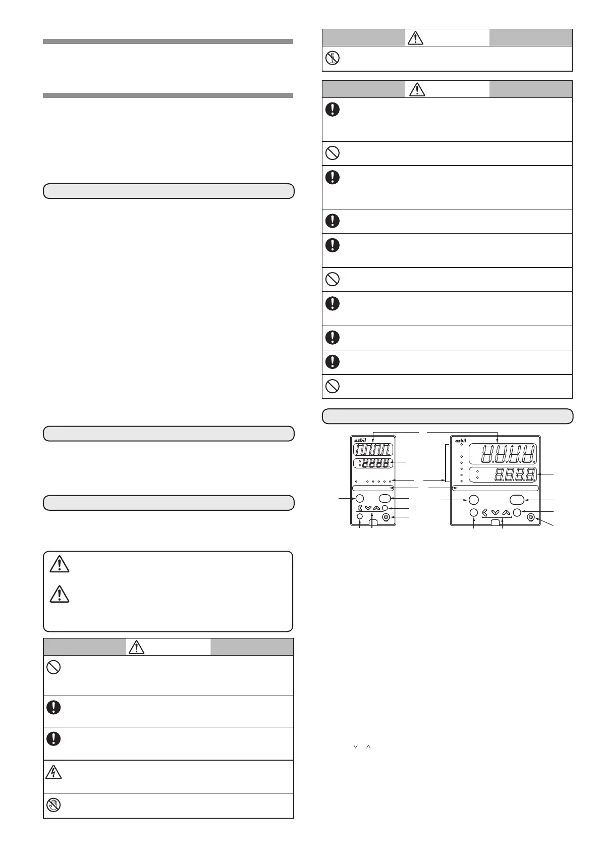
PART NAMES AND FUNCTIONS
mode
display
enter
para
man
ev1
ev2
ev3
ot1
ot2
sp
out
pv
SDC26
SDC25
man ev1 ev2 ev3 o t1 ot2
sp
out
pv
mode
display
enter
para
(2)
(3)
(6)
(9)
(10)
(6)
(9)
(10)
(2)
(4)
(5)
(1) Upper display: Displays PV values (present temperature, etc.) or
setup items.
(2) Lower display: Displays SP values (set temperature, etc.) and
other parameter values. When the lower display
shows the SP value, the “sp” lamp lights up. When
the display shows the manipulated variable (MV),
the “out” lamp lights up.
(3) Mode indicator man: Lights when MANUAL (manual mode).
ev1 to ev3: Lights when event relays are ON.
ot1, ot2: Lights when the control output is ON.
(4) MS (Multi-status) indicator:
In the combination of the lighting condition and
the lighting status as a group, the priority 3groups
can be set.
(5) [mode] key: The operation which has been set beforehand can
be done by pushing the key for 1s or more.
(6) [display] key: Used to change the display contents in the opera-
tion display mode. Display is returned from bank
setup display to operation display.
(7) [<], [
], [ ] keys: Used for incrementing numeric values and per-
forming arithmetic shift operations.
(8) [para] key: Switches the display.
(9) [enter] key: Used to set the setup values at the start of change
and during the change.
(10)
Loader connector:
Connects to a personal computer by using a dedi-
cated cable supplied with the Smart Loader
Package.
 Loading...


