General Description
© b2 electronic GmbH DHV0088 14
3 General Description
3.1 PD Basics
A long high voltage cable behaves as a wave guide. The cable has a conductor, a dielectric and a coaxial neutral (Screen
copper tape or lead) which forms an ideal wave guide. The dielectric creates a large capacitor. The longer the cable, the more
of these capacitors are in parallel. These PD waves travel down the wave guide – one PD wave to the one end of the cable
and the other PD pulse to the opposite end. If we now place a capturing device – a coupling capacitor and a Digital Storage
Oscilloscopeattheoneend,itispossibletoviewthe“timeofight”ofthesePDpulses.
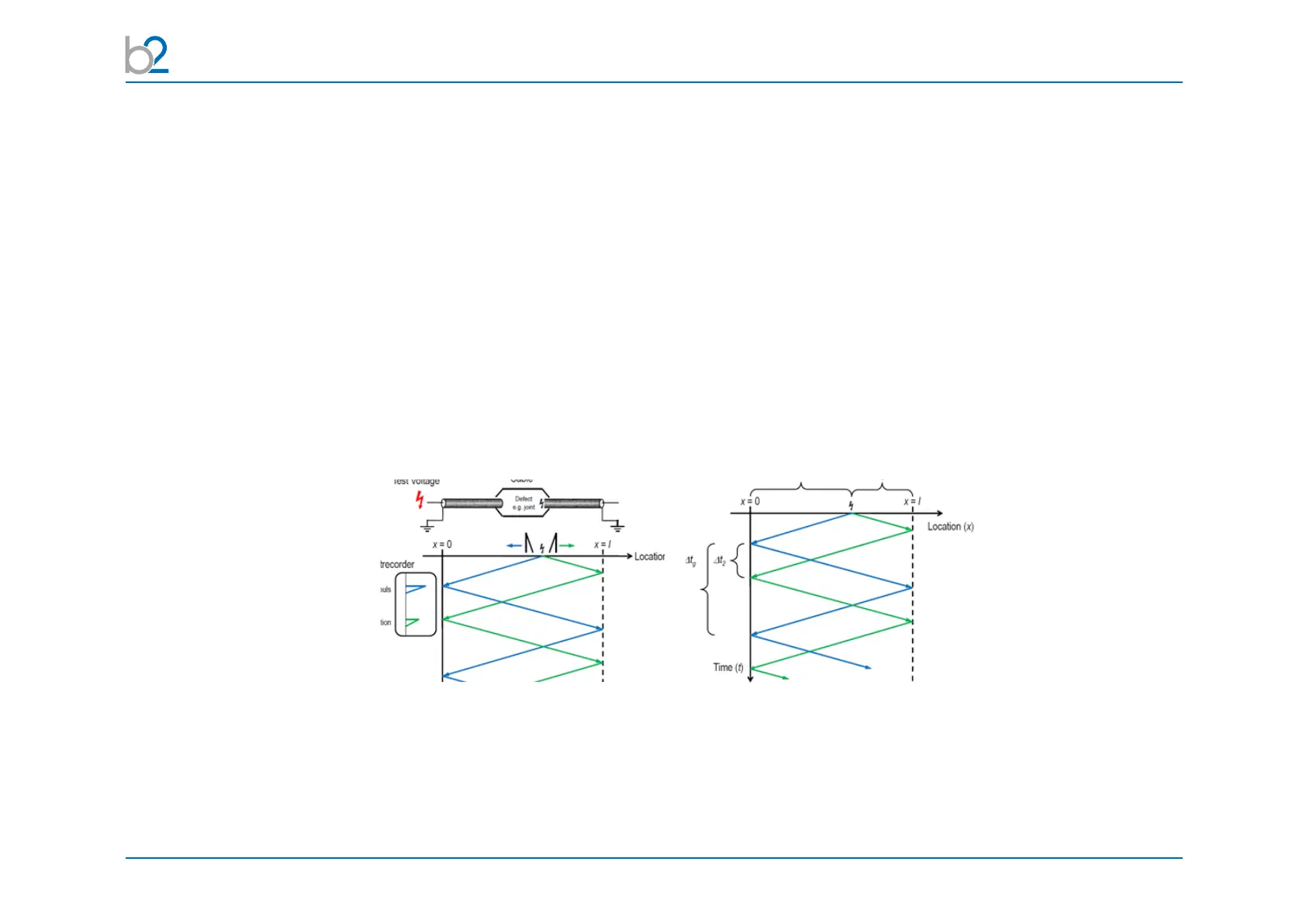
The above echogram is displayed by the Transientrecorder (b2 Suite). The 1st PD pulse (emanating from the PD source) ar-
rivesrstatthecouplingunit(seepulsemarked1stwhilstthe2ndpulsetravelstothefarend,travelsthefulllengthofthecable
andarrivesatthecouplingunit(seepulsemarked2nd).The1stpulsereectsoutofthecouplingunitandtravelstothefar
endandreectsbackhence3rdpulse.Δt2isthereforethetimedierencesbetweenthesetwoincomingpulsesandthetime
to the PD source from the far end. If we now know the velocity of propagation of the PD pulse in the cable we can calculate the
distance to the PD source ( Dist = Velocity x time )
Illustrations from Dr. Daniel Pepper
Unfortunatelyonverylongcablesthesubsequentreectionsmaybeattenuatedtosuchanextentthattheyarenotvisible.
Joint / splices also attenuate these pulses.
PILC cables have a greater attenuation on these traveling PD waves than that of a similar XLPE cable. If the returning pulse (2nd) is not
visible it is not possible to do a location. The 1st pulse only indicates that there is a discharge on the cable.
By examining the rise times of the calibration pulse and this PD pulse it is possible to determine if it is from the near end termination or not.