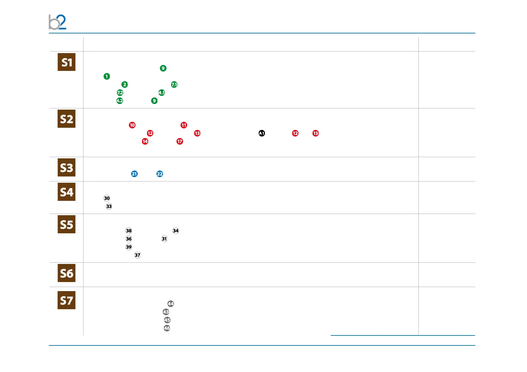
PD Test Setup
© b2 electronic GmbH DHV0088 49
Step PDTD-2 Setup -> PD Measurement (no leakage current correction) Art.Nr.
Connect all earth cables
• DUT (Device under Test)
• HVA
• PD-2 Filter and HV Cable and clamp it to MC contact at Filter
• HV cable to PD-2 CC (MC contact)
• PD-2 CC and DUT -> should be as short as possible and grounded at the same point
GH0522
GH0576 & GH0574
GH0574
GH0576
Connect HV cables
• between HVA and PD-2 Filter
• between PD-2 Filter and PD-2 CC use PD impedance
1
between and
• between PD-2 CC and DUT (connection should be as short as possible)
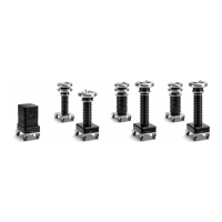
use KES0209 MC socket connection and KMD0081 corona shield for connecting to DUT
GH0801
3
, GH0581
GH0574, GH581
GH0550
2
with
KES0209&KMD0081
Connect guard cable
• from HV cable to HV (srew on MC plug at HV cable) GH0574
Connect Power Supply Plug
• HVA
• PD-2 (battery/mains); If PD is connected with power source battery is charging!
KEK0038
KEK0038
Connect Communication Ports
• between PC and PD-2 CC via USB Cable
• between PC and HVA via Opto Converter
• between PC and TD via Bluetooth (Connection possible after TD unit switched on)
• Plug b2 Dongle at PC for b2 Suite Software
GH0555
GH0624
KDG0011
GH0900
Verify Connections
• Check that all cables are attached securely.
Turn on all units
•Turn“ON”HVAmainswitch
• Turn key switch from HVA tothe“ON”position
•Turn“ON”PDmainswitch
•Turn“ON”TDmainswitch
1
except using HVA54-5,
2
for longer distance GH0550/ GH0551),
3
dependig on type of HVA