PD Test Setup
© b2 electronic GmbH DHV0088 53
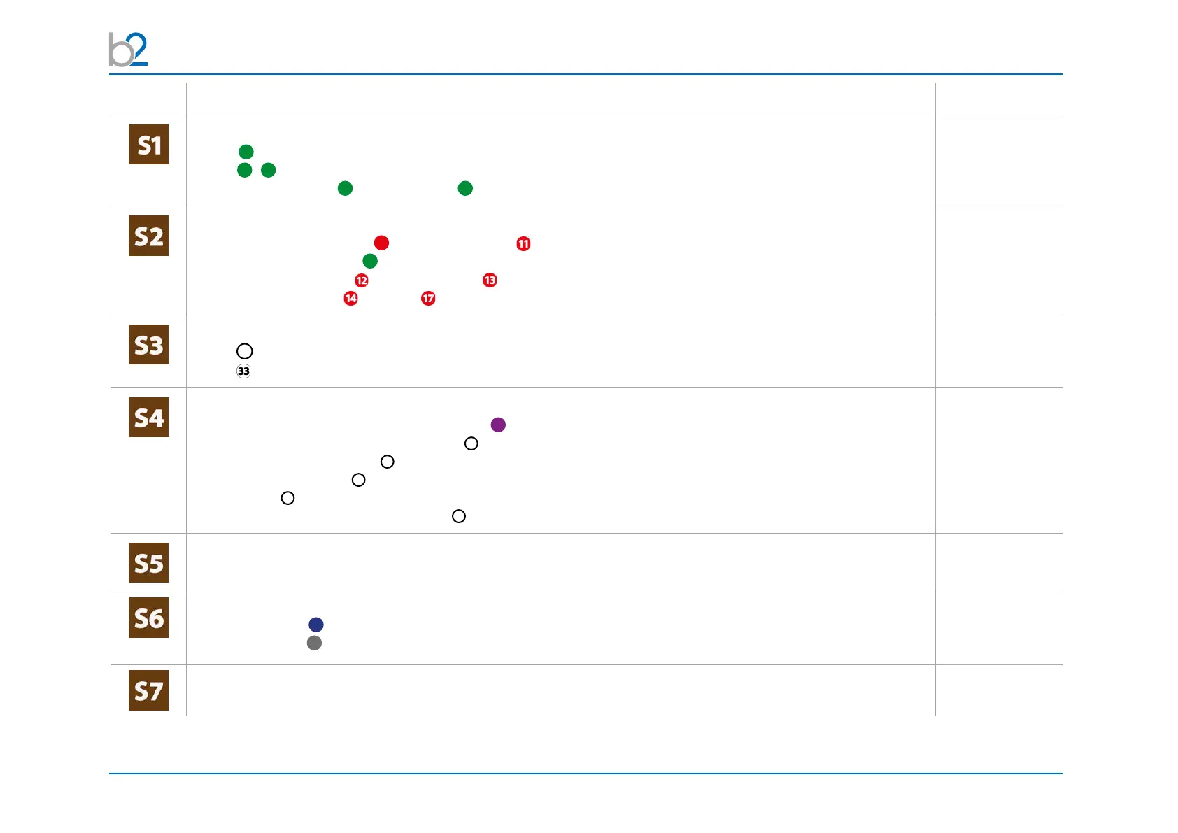
Step Procedure Art.Nr.
Connect earthing cables
• DUT
9
• HVA
1
1.1
• between PD-2 Filter
2
& PD200-2 CC
4
- should be as short as possible
Connect HV cable connections
• HV test lead between HVA
10
and PD200-2 Filter
• HV cable shield to earth
7
(only by HV Cable)
• between PD200-2 Filter and PD200-2 CC
• between PD200-2 CC and DUT (connection should be as short as possible.
Connect power suply plug
• HVA
30
• PD-2 (battery/mains); If PD is connected with power source battery is charging!
Connect Communication Ports
•betweenmeassuringtowerandbothamplier
81
(connection is for communication and power supply)
• between measuring tower and control box
31
• between control box and PC
32
• at PC - b2 Suite Dongle
37
at PC for b2 Suite Software
• between PC
39
and TD via Bluetooth (Connection possible after TD unit switched on)
• between PD-CC and PC via USB cable
38
(on cable reel)
Verify Connections
• Check that all cables are attached securely
Turn on all units
• HVA200 Display
70
• Turn key switch
43
(ontheControlBox)tothe“ON”position
The HVA system automatically boots.
• Control the HVA with the b2 Suite Software