WWW.BALTIMOREAIRCOIL.COM
27
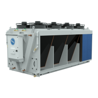
Figure 20a. Schematic for Water Flow Adjustment Screw
NOTES FOR FIGURE 19A:
1. 6 mm hexagonal adjustment
screw
2. Flow indicator
3. Water flow in l/min
4. 8 mm hexagonal set screw
Unit Operation
Start-Up
Setting the Parameters for the
Water Monitoring Option
Water Meter Set-up
Pre-Cooler Pad Water Flow
1
2
3
4
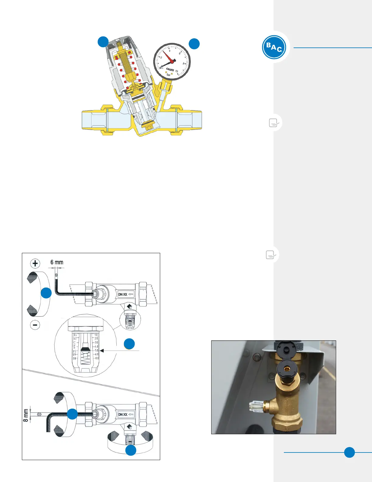
Figure 19. Make-up Pressure Balancing Valve
1
2
NOTES FOR FIGURE 18:
1. Change the pressure by rotating
the knob
2. Gauge
Flow Balancing Valves for Pumps
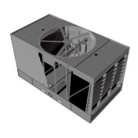
• A minimum water flow must be distributed over the Pre-Cooler Pads as per the
minimum water Flow rates (see Table 6). The water flow generated by the pumps will
depend on the size of the unit. This valve has been preset at the factory.
– First, open the plastic cover plate of the water flow adjustment screw.
– Next, loosen the set screw (8 mm hex screw).
– Then, adjust the adjustment screw (6 mm hex screw) until the correct flow is
reached.
– Finally, tighten the set screw again.
Figure 20b. Schematic for Water Flow Adjustment Screw