WWW.BALTIMOREAIRCOIL.COM
55
Type Screen Name Description
Default
Value
Adjustable
Range Comments
Diagnostics Mode - Technician Menu Continued
M Fan Speed Manually adjust fan speed 0-100% —
V Conductivity
[1]
Conductivity of basin water (0-2000μS). Only present w/ "Water Monitoring Package" (See page 28)
[1]
M Drain Time
Duration of the periodic flush
used for bleed
120 sec TSDC
480 sec
TSDC2
0-999 sec
CAUTION: Lowering this value may result in scaling the unit. Increasing this value may result in
increased water usage
M Cycle
How far apart the periodic flush
cycles are
2 hrs 1-22 hrs NOTE: This variable is not used with the "Water Saver" Option
V Pump On Delay
Delay after float switch closes
before pump turns on
5 sec 0-20 sec —
V
Pump/Make-up
Delay
Delay after float switch opens
before pump turns off
35 sec TSDC
100 sec
TSDC2
0-999 sec —
V Make-up on Delay
Delay after float switch opens
before Make-up valve opens
30 sec TSDC
10 sec TSDC2
0-99 sec —
V Make-up off Delay
Delay after float switch closes
before Make-up valve turns off
10 sec
TSDC
30 sec TSDC2
0-999 sec
CAUTION: Increasing this value may result in increased water usage, with water spilling into the
overflow
V Pump Fail Delay
Allowable delay between pump
activation and pump proof
received before alarm trips
30 sec 0-999 sec —
V Press Fail Delay
Allowable delay between sensor
signal going above/below
acceptable range and alarm
tripping
10 sec 0-999 sec —
V Make-up Fail Delay
Allowable time for Make-up to
be on and float-switch to not
be made before alarm trips
180 sec TSDC
1,800 TSDC2
0-2,000 sec
M
High Head Pressure
Alarm Setpoint
[1]
High head pressure alarm
setpoint
500psi 0-3000psi Only present w/ 'Head Pressure' Control Option (see page 15)
[1]
M
High Head Pressure
Alarm Delay
[1]
Delay before high pressure
alarm activates
30 sec 0-999 sec Only present w/ ‘Head Pressure’ Control Option (see page 15)
[1]
M
Antifreeze protection
setpoint
Temperature below which Pre-
Cooler Mode is disabled
40°F 0-100°F
WARNING: Adjusting this value to below 35°F will void the warranty, and may cause damage to
the unit. Increasing the value will limit the wet operation.
M Gas Pressure
[1]
— — — Only present w/ ‘Head Pressure’ Control Option (see page 15)
[1]
M Gas Temperature
[1]
— — — Only present w/ ‘Head Pressure’ Control Option (see page 15)
[1]
V
Fan Power, Voltage,
Current, Motor Temp
Fan/Motor information — — —
Manual Control - Technician Menu
V Pump Proof
Check whether pump is
energized
— — —
V Float Switch
Check whether float switch
is made
— — —
M Water Pump Manually turn on/off pump — Open/Closed —
M Dump Valve
Manually turn on/off dump
valve
— Open/Closed —
M Make-up valve
Manually turn on/off make-up
valve
— Open/Closed —
V Fan Request
Fan Speed control voltage that
the controller receives from
customer analog input
—
0-10V/10-
0V/4-20mA
—
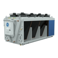
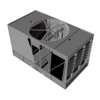
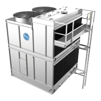
TRILLIUMSERIES™ ADIABATIC CONDENSER
Appendix: Danfoss and
Emerson CPC Rack Controllers
b
The settings shown below for Danfoss and Emerson CPC are recommended starting
settings based on BAC’s experience with TrilliumSeries™ Products in the field. However,
all sites are different and may require additional tuning. Please contact BAC for additional
assistance if required.
Danfoss
Step 1. From the Main Menu select Configuration. Step 2. From Configuration select Refrigeration.
Step 3. From Rack Configuration select Rack. Step 4. From Configure Rack select Condensers.