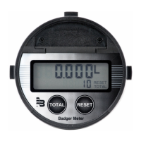
INSTALLATION
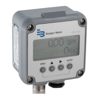
Connecting the ER-500 Monitor to a Pulse Output Device
The ER-500 monitor has two jumpers that are used to set the type of signal and the minimum amplitude of the signal that
it accepts. When used with Badger Meter IOG oval gear meters, the Input Signal Level should be set to Low and the Input
Waveform should be set for pulse as shown in Figure 2.
JP1
JP2
JP3
Input Total Pulse Signal
Mag
Pulse
Iso
OC
Low
High
Input Waveform Selection
(Should be set to Pulse for IOG meter)
Input Signal Level Selection
(Should be set to Low for IOG Meter)
Figure 2: Input jumper settings
If the ER-500 monitor is a replacement, it must be calibrated for the IOG it is intended to be used with. The K-factor for the
specific IOG meter must be programmed into the ER-500 monitor. The K-factor value is found on the calibration certificate
that came with the IOG meter. For instructions on programming the K-factor, see Enter Flow Sensor's K-factor* on page 17.
Transmitter Connections
The ILR transmitter typically used with the IOG meter family has two sets of pulse output wires. The white and green output
leads connected to the primary reed switch bank are generally the first choice (see Figure 3).
JP1
JP2
JP3
Input Total Pulse Signal
P1
Freq. In
4-20mA
Iso Total Pluse
TR_B
TR_A
RS485 Gnd
Setpoint 1
Setpoint 2
Gnd
+
–
+
–
+
–
Total Reset
OC Total Pluse
Signal Gnd
TB1
Mag
Pulse
Iso
OC
Low
High
Freq. In
Gnd
Mag
Pulse
+
–
Reed Switch
Bank
ILR
Pulse Transmitter
White
Green
Blue
Black
Switch Bank
Figure 3: Typical IOG meter input connection
The ILR transmitter also has a secondary (auxiliary) set of pulse output wires. Either pair can be used to connect to the ER-500
monitor. The connections are:
ILR Wires
ER-500 Terminals Reed Switch Bank (Primary) Reed Switch Bank (Auxiliary)
Freq. In + White Blue
Freq. In - Green Black
Installation
DSY-PM-00028-EN-02 Page 7 February 2017
 Loading...