Wiring diagram LM OG-TAE(R) 2 x 100 / Changing the battery Page 13/28
LM_OG_BA_98_1105
R1K2
1K2R
AUSG.1
OUT 1
OUT 2
AUSG.2
0V
GND
6-24 VDC
SUPPLY
OG-TAER 200
GRÜN
GREEN
WHITE
WEISS
BROWN
BRAUN
YELLOW
GELB
6. Wiring diagram LM OG-TAE(R) 2 x 100
LM OG-TAE(R) 2 x 100
Art. n° 102128, 102130, 102131, 103132
The wiring configuration is different for the meters 102128
and 102130 to: channel 1 =
white; channel 2 = green
Wiring diagram
LM OG-T 100 / LM OG-HFT 1“ / LM OG-HFT LM OG-T 2 x 100
66,75 PPL Art. n° 102101 / 102920 / 102915 Art. n° 102106
Wiring diagram Wiring diagram
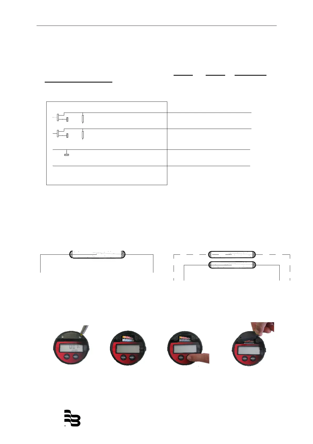
7. Changing the battery
If you change the battery, please proceed as follows:
Battery: Lithium CR123A
Picture 1: Loosen
the battery cover
Picture 2: Take out
the battery
Picture 3: Insert the new
battery and press the reset
button to check the function
of the register
Picture 4: Insert the
battery cover, then screw
the battery
Reedswitch
yellow
white
brown
green
Reedswitch
white brown

 Loading...