Page 17
4-11
Installation & Operation Manual
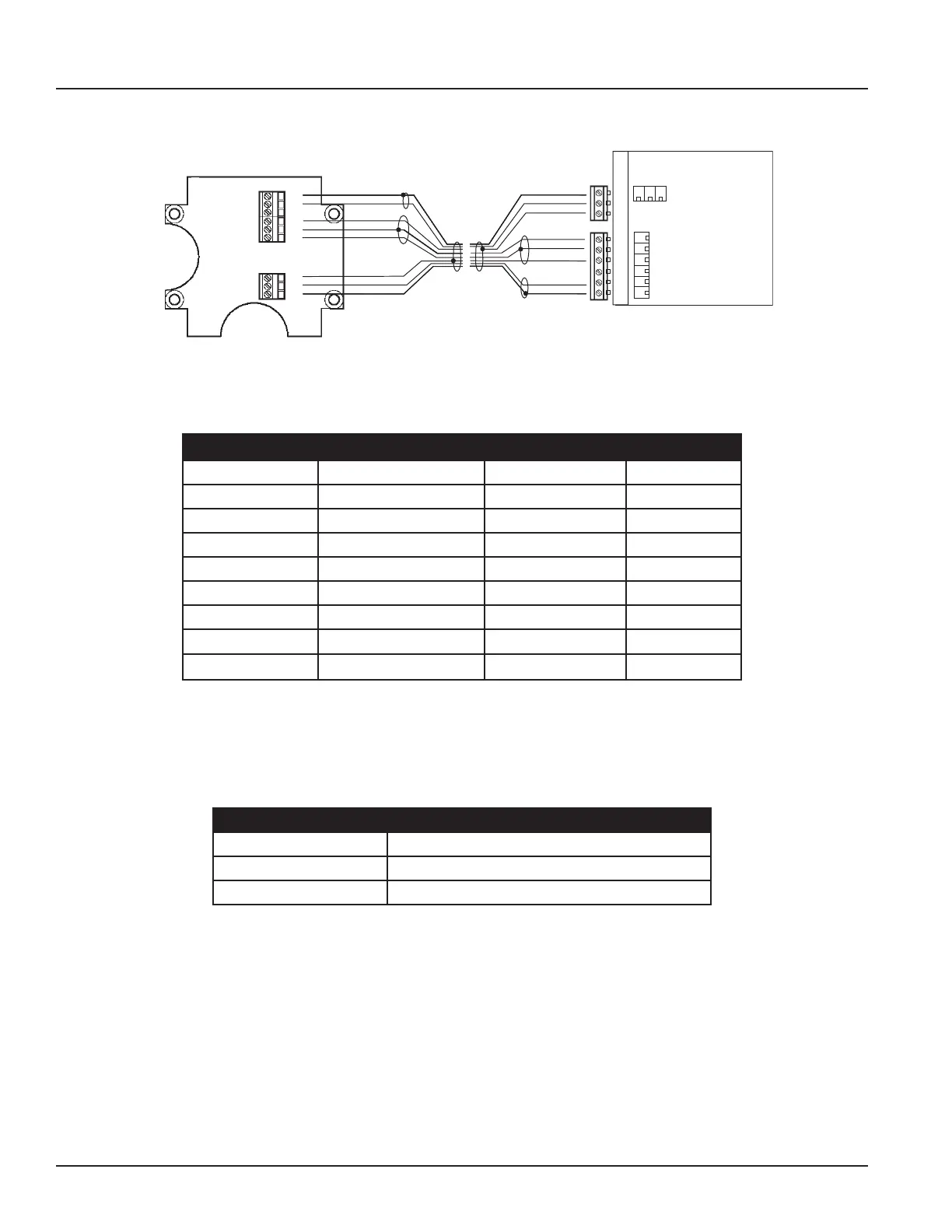
Wiring for Remote Configuration
44
40
44
46
44
45
13
12
11
shield (black)
pink
brown
shield (black)
white
shield (black)
yellow
green
green
yellow
shield (black)
white
shield (black)
brown
pink
shield (black)
E1
ES
E2
RS
EP
ES
CS C2 C1
Remote style M-2000 amplifier models can be ordered with standard cables measuring 15, 30, 50 and 100 feet. In addition,
cables up to 500 feet are available.
Junction Box Amplifier
Connection No. Description Wire Color Connection
11 Coil Green C1
12 Coil Yellow C2
13 Main Shield Black (Red Ferrul) CS
45 Electrode White E1
44* Electrode Shield Black ES
46 Electrode Brown E2
40
Empty Pipe
Pink EP
44*
Empty Pipe Shield
Black ES
*Connections with the No. 44 are lying on the same potential.
Empty Pipe Detection Considerations
Take into account the following cable length and conductivity requirments, if you will be using empty pipe detection.
Cable Length (Feet) Minimum Conductivity Required (µS/cm)
0* 5
100 20
500 100
* Meter Mount

 Loading...


