Page 19
4-11
Installation & Operation Manual
Input/Output Description Terminal
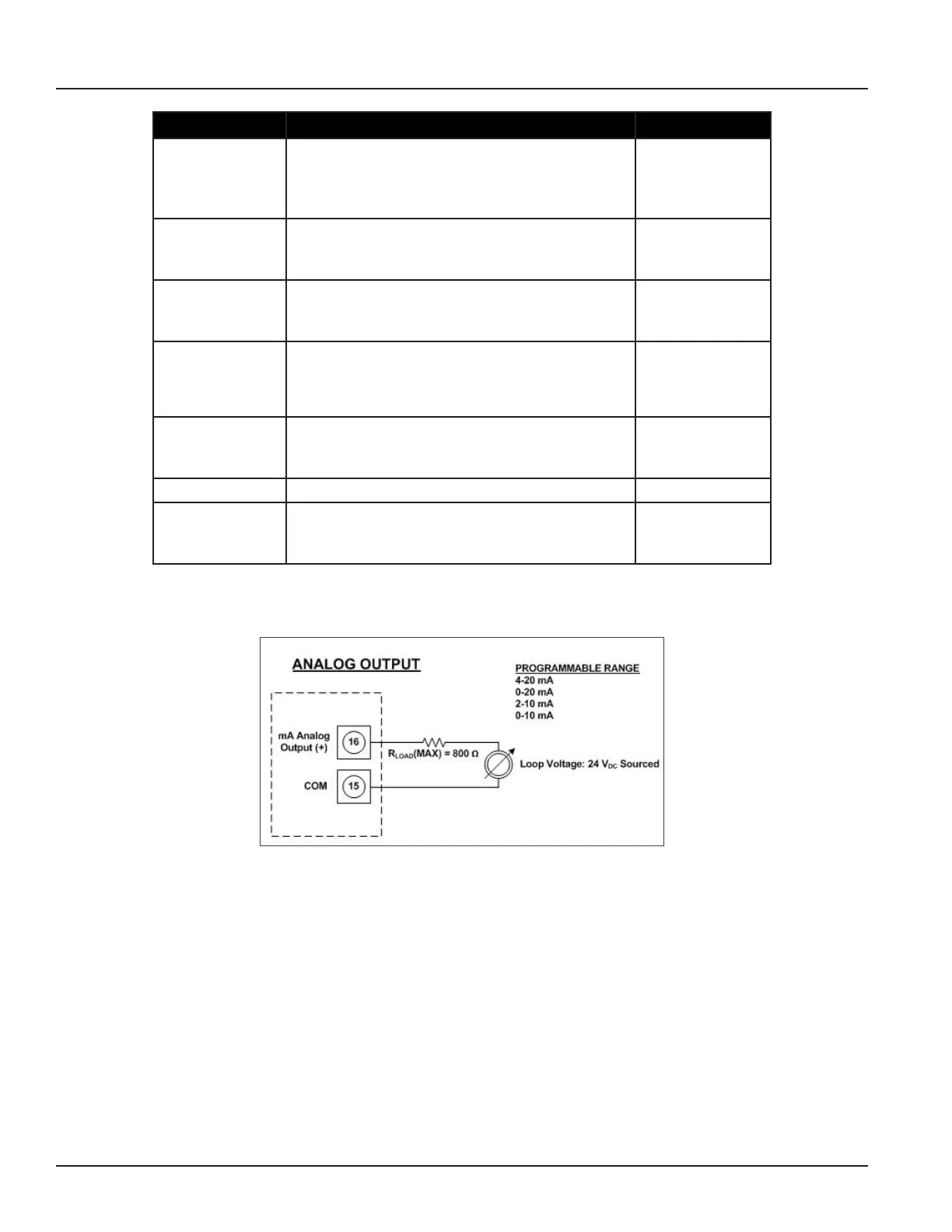
Analog Output 0-20 mA Resistive Load < 800 ohms
4-20 mA Resistive Load < 800 ohms
0-10 mA Resistive Load < 800 ohms
2-20 mA Resistive Load < 800 ohms
16 (+)
15 (-)
Digital Output 1 Passive max. 30 VDC, 100 mA
Active 24 VDC, 50 mA (set Jumper JP1)
Max. Frequency 10 kHz
1 (+) and 2 (-)
Digital Output 2 Passive max. 30 VDC, 100 mA
Active 24 VDC, 50 mA (set Jumper JP2)
Max. Frequency 10 kHz
3 (+) and 4 (-)
Digital Output 3 Passive Max 30 VDC, 100 mA, 10 kHz
Solid State Relay 48 VAC, 500 mA, 1 kHz
* Software configurable
10 (+) and 9 (-)
10 (+) and 11 (-)
Digital Output 4 Passive Max 30 VDC, 100 mA, 10 kHz
Solid State Relay 48 VAC, 500 mA, 1 kHz
* Software configurable
13 (+) and 12 (-)
13 (+) and 14 (-)
Digital Input 5 - 30 VDC 8 (+) and 9 (-)
Communications
(Port A)
RS232, configurable, Modbus RTU or RDI. 7 GND
6 Rx
5 Tx
Analog Output Wiring Diagram
 Loading...


