39
AL-KO COUPLING
OVERRUNNING DEVICE
The device housing is packed with grease on
assembly, but will require periodic maintenance
to ensure smooth operation of the braking
system.
• Re-grease the shaft bearings via the grease
nipples provided at 3,000 mile intervals, and
before storage.
• Ensure correct functioning of all pivot pins
and levers, and oil regularly.
• Ensure correct functioning of handbrake
ratchet and oil regularly.
JOCKEY WHEEL
Lubricate wheel and screw thread periodically
with grease.
BRAKE LINKAGE
All moving parts should be lubricated
periodically to ensure their satisfactory
operation.
CORNER STEADIES
The screw and pivot pins should be lubricated
periodically to ensure their satisfactory
operation.
BRAKING SYSTEM ADJUSTMENT
(At 500 miles, then every 3,000 miles or 1
year)
1. Ensure the towing shaft with coupling heads
is pulled fully forward.
2. Release the handbrake to the fully off
position. If the handbrake will not go down the
whole way because of the fairing or any other
obstruction then the fairing must be cut away
and/or the obstruction removed to achieve
this desired position. It will not be possible
to set up the braking system properly when
the handbrake is not in the fully off position
(fig. 8).
3. Jack up one side of the caravan (see Jack
Operation Instructions).
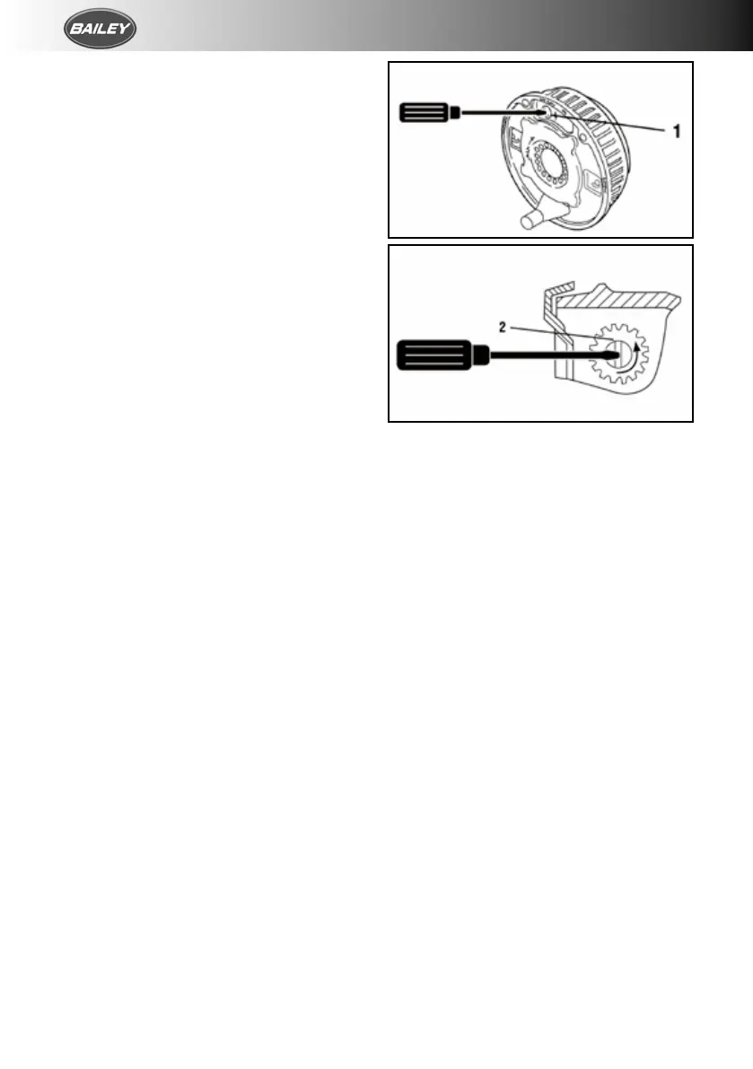
4. Remove the inner plastic bung from the
backplate to expose the “star-wheel” adjuster
access (fig. 8).
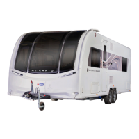
FIG 8.
5. Rotating the road wheel in the forward
direction (never backwards), adjust the
star-wheel with a suitable screwdriver in
the direction of the arrow embossed on the
backplate until there is resistance in the wheel
rotation (fig. 8).
6. Slacken off the star-wheel adjuster until the
road wheel turns freely in the forward direction
(fig. 8).
7. Check the adjustment at the end of the brake
cable where it is secured to the abutment
(bracket) welded to the centre of the axle.
When the inner cable is pulled out it should
extend between 5 and 8 mm. (On tandem axles
a double abutment is fitted to the front axle
only).
8. Repeat for other wheel or wheels.