11
11
english
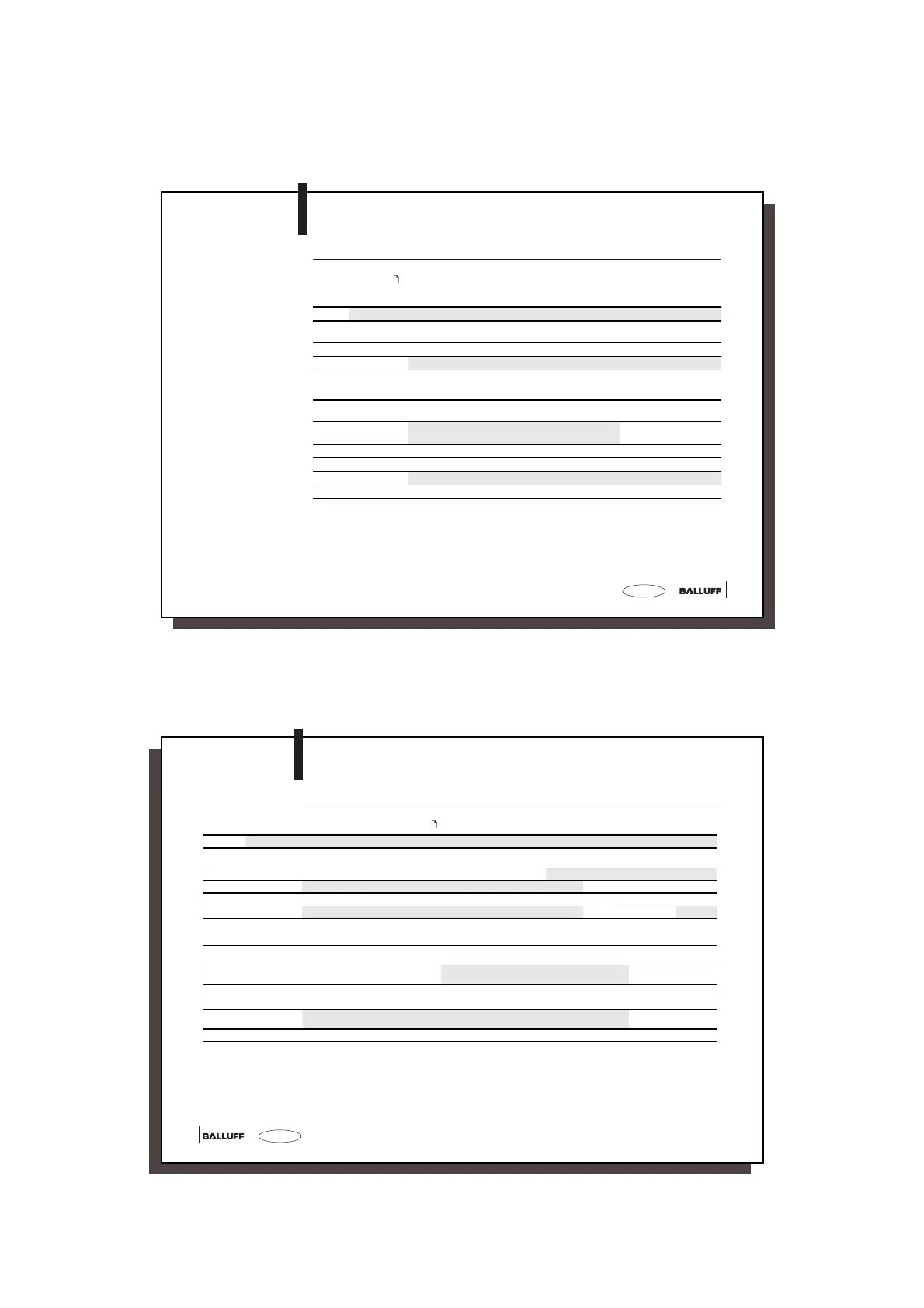
Tabular Overview
The table lists read/write heads which can be flush mounted in steel. For notes on installing
in aluminium, see
14. The read/write orientation may be any, since a round antenna form
is used for these read/write heads.
Selection Criteria
Read/Write Heads Series BIS C-3_ _
Criteria Ty pe s:
1)
BIS C-300-_ _ C-306-_ _ C-302-_ _ C-305-_ _ C-315-_ _ C-325/_ _-S4 C-324/_ _-S4
Size [mm] Ø 14.5 × 55 M16×1
× 55
61.5 × 33
× 40
50 × 25
× 10
80 × 80
× 40
M18×1
× 45
40 × 41
×74.5
Distance
2)
[mm] 32 32 32 40 180 60 60
Enclosure per IEC 60529 IP 67
Housing material
CuZn
Nickel
plated
Brass
Nickel
plated
Al Mg3 /
PA66
ABS-GF16 Plastic PBT X6CrNiMoTi
17-12-2
Plastic PBT
Mounting
2 nuts SW
Screws
secure in
slot
22
2 × M4 2 × M4 4 × M5
24
2 × M5
Connection to the
BIS C-6_ _
direct, using molded-on connection cable
with 4-pin connector
using a connection cable
3)
Cable length
1)
[m] 1, 5, 10 1, 5, 10 5, 10 1, 5, 10 1, 5, 10 1, 5, 10 5, 10
Cable material
PU PU PU PVC/PU PVC/PU
3) 3)
Temperature Ambient 0 °C to +70 °C / storage –20 °C to +85 °C
Weight [g] 210 200 270 230 510 26 180
1)
in the part number for read/write head, _ _ is for inserting the desired cable length:
01 = 1 m, 05 = 5 m, 10 = 10 m
2)
The distance is defined as free space between two read/write heads of equal size. When the two read/write
heads differ in size or when the data carrier is larger than the read/write head, the distance of the larger
device has to be applied.
3)
appropriate connector cable: BIS C-505-PU-_ _ / BIS C-506-PU-_ _ / BIS C-517-PVC-_ _ / BIS C-518-PVC-_ _
For details, see ordering information for cable and connectors
C3-slk_716464_E_1110.p65
12
english12
Tabular
Overview
The table lists read/write heads which cannot be flush mounted in steel. For notes on
installing in aluminium, see
14.
Selection Criteria
Read/Write Heads Series BIS C-3_ _
Criteria Ty pe s:
1)
BIS C-319/_ _-S4 C-323/_ _-S4 C-315/_ _-S4 C-319-_ _ C-326-_ _ C-310-_ _ C-318-_ _ C-351-_ _ C-355/05-S92 C-350-00,3
Size [mm] M18×1
× 86.5
M30×1.5
× 70.5
80 × 106
× 40
M18×1
× 80
M30×1.5
× 83,5
M30×1.5
× 70
186 × 48
× 30
170 × 80 240 × 120
× 60
240 × 120
× 60
Read/write orientation non-directional
directional
Antenna form
round Bar Bar
2)
Bar
Distance
3)
[mm] 180 180 180 180 60 60 1000 1000 1000 2000
Enclosure per DIN 40 050
IP 67 IP 65 IP 67
Housing material Plastic
PBT
X8CrNiS 18-9 Plastic
PBT
Plastic
PBT
Plastic
PVDF
CuZn
Nickel
plated
Plastic
PA6 6
Polyacetat Plastic
PC
Plastic PC
Mounting
2 nuts SW
Screws
24 36
4 × M5
24 36 36
4 × M5 4 × M6 4 × M4 4 × M4
Connection to the BIS C-6_ _ using a connection cable
4)
direct, using moded-on connection cable
with 4-pin connector
5) 6)
Cable length
[m] 1, 5, 10 5, 10 5, 10 1, 5, 10 5, 10 1, 5, 10 5, 10 5, 10 5 0.3
Cable material
4) 4) 4)
PU PU PU PU PU
5)
PU
Temperature ambient
storage
[°C]
0 to +70
-20 to +85
0 to +70
-20 to +85
0 to +40
-20 to +85
Weight
[g] 40 90 410 197 270 314 550 595 710 967
1)
In the part number for read/write heads, _ _ is for inserting the desired cable length: 01 = 1 m, 05 = 5 m, 10 = 10 m
2)
-Double antenna for increased traverse speed
3)
The distance is defined as free space between two read/write heads of equal size. When the two read/write heads differ in size or when the data carrier is larger
than the read/writre head, the distance of the larger device has to be applied.
4)
appropriate connector cable: BIS C-505-PU-_ _ / BIS C-506-PU-_ _ / BIS C-517-PVC-_ _ / BIS C-518-PVC-_ _
For details, see ordering information for cable and connectors
5)
only with BIS C-520-PVC-05 with 5-pin connector
6)
only with BIS C-516-PU-_ _ with 8-pin connector
 Loading...