15
15
english
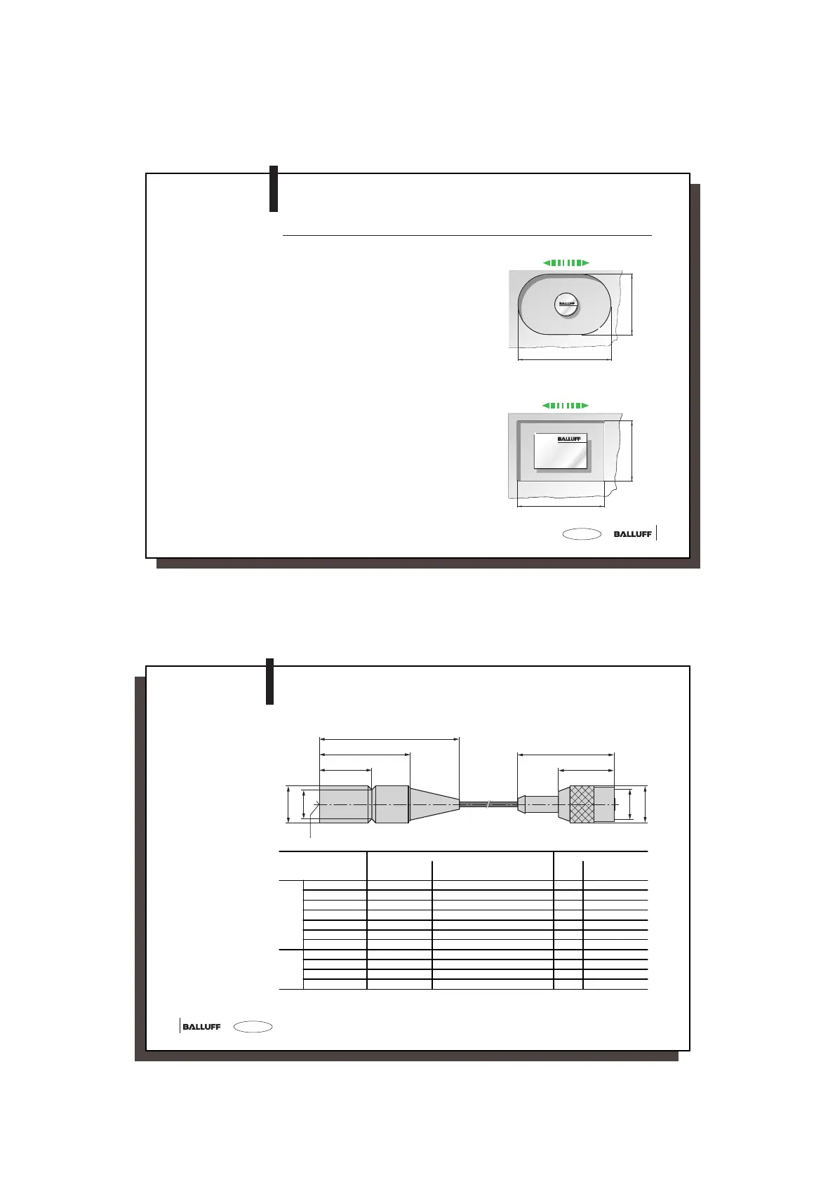
Installation in Aluminium
With Clear Zone,
Dynamic Operation
In dynamic mode the depth of the clear zone in
aluminum must also be at least 10 mm.
Fig. 1
The clear zone dimension A corresponds to 2x
the diameter of the larger communication partner
plus 1x the diameter of the smaller
communication partner. The clear zone
dimension C corresponds to the diameter of the
larger communication partner plus the
corresponding maximum offset (see
specification for read/write head).
Fig. 4
In combination with read/write heads BIS C-318,
327, 328, 350, 351 and 355, dimension B is
calculated as 2x the read/write travel (see
specification for read/write heads) plus the width
of the data carrier. The clear zone dimension C
corresponds to the read/write head length plus
the corresponding maximum offset (see
specification for read/write head).
Fig. 5
Read/write travel
Fig. 4
A
C
Fig. 5
Read/write travel
B
C
C3-slk_716464_E_1110.p65
16
english16
Dimensions
Standard:
Length _ _
01 = 1 m
05 = 5 m
10 = 10 m
55
35
20
42
24
L=__
Ø 14.5
Ø 14.5
Ø11
M12×1
Sensing surface
Read/Write Head
BIS C-300-_ _
Distances and
Velocities between
Read/Write Head
and matching
Data Carrier
1)
The indicated relative speeds assume a read or write of the first 4 bytes of the data carrier (bytes 0...3).
2)
This data carrier is appropriate for installation in aluminum. Dynamic operation not permitted!
Matching Data Carrier Static Mode (V = 0) Dynamic Mode (V > 0)
Distance [mm] Offset [mm] at a distance [mm] of
Distance
[mm]
Vmax. [m/min]
1)
Read Write 0.7 1 3 5 7 10 Read Write
for
flush
moun-
ting
in
steel
BIS C-100-05/A
2)
0 to 4 0 to 4 ± 3 ± 2 1 8
BIS C-103-05/A
2)
0 to 3.5 0 to 3.5 ± 3 ± 2 1 6
BIS C-105-05/A
2)
0 to 3.5 0 to 3.5 ± 3 ± 2 1 6
BIS C-121-04/L 0 to 2 0 to 2 ± 2 1 6
BIS C-121-04/L-SA1 0 to 1.2 0 to 1.2 ± 2
BIS C-122-04/L 0 to 2.5 0 to 2.5 ± 2.5 1 6
BIS C-130-05/L 0 to 4 0 to 4 ± 3,5 ± 3 1 to 3 7
non-
flush
BIS C-130-05/L 0 to 4 0 to 4 ± 5 ± 3 1 to 3 10 to 8 7 to 5
BIS C-130-05/L-SA1 0 to 4 0 to 4 ± 5 ± 4 1 to 3 10 to 8 7 to 5
BIS C-130-05/L-SA2 0 to 3,2 0 to 3,2 ± 4 ± 3 1 to 2 8 to 7 5 to 4
BIS C-191-_ _/L 0 to 3.5 0 to 3.5 ± 4 ± 3 1 to 3 10 to 7 6 to 4
 Loading...