13
13
english
Distance between
neighboring
Data Carrier
The distance between two data carriers is defined as the free space between two data carriers of equal size.
When the data carriers differ in size or when the read/write head is larger the distance of the larger device has
to be applied.
For dynamic mode V has to be in [m/min].
For distances between read/write heads see previous page.
Data Carrier
Type
Minimal Distance [mm] for
static Mode
V = 0 m/min
dynamic Mode
V > 0 m/min
BIS C-100.../A 32 V
dyn
+ 37
BIS C-103.../A 32 V
dyn
+ 37
BIS C-104.../A 60 V
dyn
+ 65
BIS C-105.../A 32 V
dyn
+ 37
BIS C-108.../L 120 V
dyn
+ 125
BIS C-108.../L-SA2 120 V
dyn
+ 125
BIS C-117.../A 60 V
dyn
+ 65
BIS C-117.../L 120 V
dyn
+ 125
BIS C-121.../L 32 V
dyn
+ 37
BIS C-121-04/L-SA1 32 V
dyn
+ 37
BIS C-122.../L 32 V
dyn
+ 37
Data Carrier
Type
Minimal Distance [mm] for
static Mode
V = 0 m/min
dynamic Mode
V > 0 m/min
BIS C-126.../L 120 V
dyn
+ 125
BIS C-127.../L 340 V
dyn
+ 345
BIS C-128.../L 120 V
dyn
+ 125
BIS C-130.../L 64 V
dyn
+ 69
BIS C-130-05/L-SA1 64 V
dyn
+ 69
BIS C-130-05/L-SA2 64 V
dyn
+ 69
BIS C-133.../L 120 V
dyn
+ 125
BIS C-150 with
BIS C-351 or
BIS C-653
270 V
dyn
+ 275
BIS C-190.../L 120 V
dyn
+ 125
BIS C-191.../L 64 V
dyn
+ 69
Selection Criteria
Read/Write Heads Series BIS C-3_ _
C3-slk_716464_E_1110.p65
14
english14
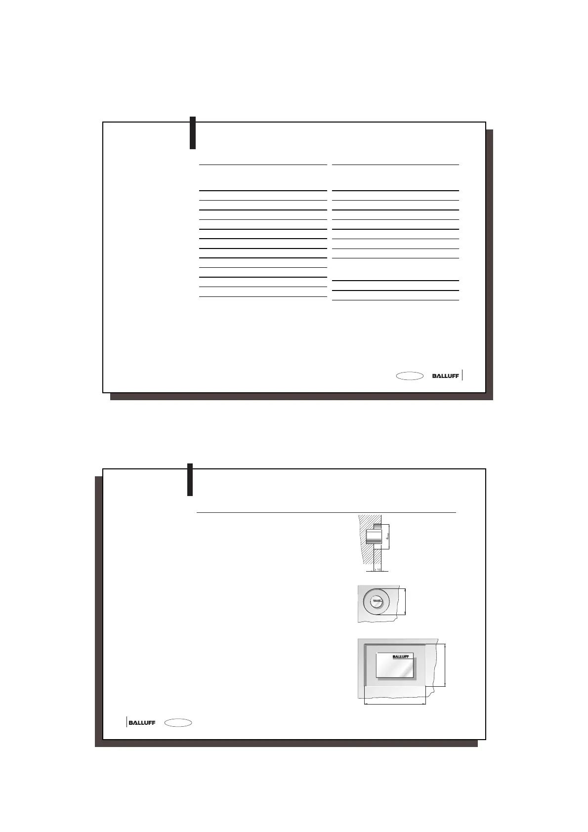
Installation in Aluminum
With Clear Zone,
Static Operation
When installing the components in aluminum,
provide clear zones for fault-free operation.
In static operation the depth of the clear zone in
aluminum must be kept to at least 10 mm.
Fig. 1
The clear zone dimension A corresponds to 2x
the diameter of the larger communication partner
plus 1x the diameter of the smaller
communication partner (see specification for read/
write head).
Fig. 2
In combination with read/write heads BIS C-318,
327, 328, 350, 351 and 355 the dimensions B
and C are calculated using the length and width
of the larger communication partner (data carrier
or read/write head) plus the maximum possible
offset (see specification for read/write head).
Fig. 3
A
Fig. 2
Fig. 1
Fig. 3
B
C
 Loading...