23
23
english
Ø m 60
M30×1,5
36
13
[ 13
50
70
42
24
Ø 14.5
M12×1
L=__
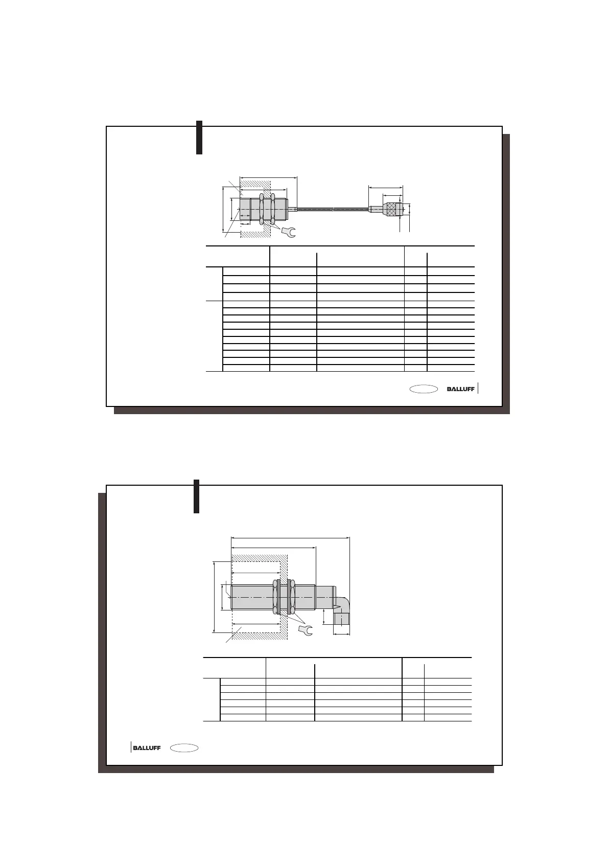
Read/Write Head
BIS C-310-_ _
Clear zone
in metal
Sensing surface
Dimensions
Standard:
Length _ _
01 = 1 m
05 = 5 m
10 = 10 m
Distances and
Velocities between
Read/Write Head
and matching
Data Carrier
Matching Data Carrier Static Mode (V = 0) Dynamic Mode (V > 0)
Distance [mm] Offset [mm] at a distance [mm] of
Distance
[mm]
Vmax. [m/min]
1)
Read Write 0.7 1 3 5 7 10 Read Write
for
flush
moun-
ting
in
steel
BIS C-104-_ _/A
2)
1 to 11 1 to 11 ± 7.5 ± 7 ± 7 ± 7 3 to 7 17 10
BIS C-117-05/A
2)
1 to 12 1 to 12 ± 7.5 ± 7.5 ± 7 ± 6.5 3 to 7 17 to 16 13
BIS C-128-_ _/L 0 to 8 0 to 8 ± 8 ± 7 ± 6.5 ± 5.5 1 to 5 19 to 16 11 to 9
BIS C-130-05/L-SA1 0 to 8 0 to 8 ± 6.5 ± 6 ± 5.5 1 to 5 16 to 14 9 to 8
non-
flush
BIS C-104-_ _/A 0 to 12 0 to 12 ± 7.5 ± 7 ± 7 ± 7 3 to 7 17 10
BIS C-108-_ _/L 0 to 12 0 to 12 ± 10 ± 9 ± 9 ± 8.5 1 to 7 24 to 22 14 to 12
BIS C-108-_ _/L-SA2 0 to 11 0 to 11 ± 10 ± 9 ± 8.5 ± 7.5 1 to 7 24 to 17 14 to 10
BIS C-117-05/L 0 to 13 0 to 13 ± 11 ± 10 ± 10 ± 9.5 1 to 7 27 to 24 15 to 14
BIS C-128-_ _/L 0 to 13 0 to 13 ± 10 ± 10 ± 9 ± 9 1 to 7 24 to 22 14 to 11
BIS C-130-05/L 0 to 11 0 to 11 ± 9 ± 8 ± 7 ± 5 1 to 7 23 to 12 13 to 7
BIS C-130-05/L-SA2 0 to 10 0 to 10 ± 9 ± 8 ± 7 ± 4 1 to 7 23 to 10 13 to 5
BIS C-133-_ _/L 0 to 10 0 to 10 ± 10 ± 9 ± 9 ± 7 1 to 7 24 to 17 14 to 10
BIS C-190-_ _/L 0 to 11 0 to 11 ± 10 ± 9 ± 9 ± 8 ± 6.5 1 to 10 25 to 16 14 to 9
BIS C-191-_ _/L 0 to 10 0 to 10 ± 8 ± 7,5 ± 7 ± 6.5 1 to 7 20 to 16 11 to 9
1)
The indicated relative speeds assume a read or write of the first 4 bytes of the data carrier (bytes 0...3).
2)
This data carrier is appropriate for installation in aluminum. Dynamic operation not permitted!
C3-slk_716464_E_1110.p65
24
english24
Read/Write Head
BIS C-319/_ _-S4
Dimensions
Standard:
Length _ _
01 = 1 m
05 = 5 m
10 = 10 m
Compatible
connection cable
2)
Distances and
Velocities between
Read/Write Head
and matching
Data Carrier
1)
The indicated relative speeds assume a read or write of the first 4 bytes of the data carrier (bytes 0...3).
2)
BIS C-505-PU-_ _ / BIS C_506-PU-_ _ / BIS C-517-PVC-_ _ / BIS C-518-PVC-_ _
Matching Data Carrier Static Mode (V = 0) Dynamic Mode (V > 0)
Distance [mm] Offset [mm] at a distance [mm] of Distance
[mm]
Vmax. [m/min]
1)
Read Write 1 3 5 7 10 15 Read Write
non-
flush
BIS C-108-_ _/L 0 to 14 0 to 14 ± 12 ± 12 ± 11 ± 11 ± 9 0 to 10 26 to 20 17 to 13
BIS C-117-05/L 0 to 15 0 to 15 ± 13 ± 12 ± 12 ± 11 ± 10 0 to 10 31 to 22 18 to 15
BIS C-130-05/L 0 to 13 0 to 13 ± 9 ± 9 ± 9 ± 8.5 ± 7.5 0 to 10 23 to 19 13 to 11
BIS C-130-05/L-SA1 0 to 13 0 to 13 ± 9 ± 9 ± 9 ± 8.5 ± 7.5 0 to 10 23 to 19 13 to 11
BIS C-130-05/L-SA2 0 to 12 0 to 12 ± 9 ± 9 ± 9 ± 8 ± 6 0 to 9 23 to 19 13 to 11
BIS C-190-_ _/L 0 to 11 0 to 11 ± 9 ± 9 ± 9 ± 8 0 to 8 22 to 20 13 to 11
86.5
35
[ 35
Ø m 50
60
12
M12×1
24
M18×1
Clear zone
in metal
Sensing
surface
 Loading...