WWW.BALLUFF.COM • 1-800-543-8390
9
™
BTL5-A/C/E/G_ _-M/U_ _ _ _-P-S 32/KA_ _
Micropulse Linear Position Transducer
Analog Output/ Profile Housing
55
28
45
21
Ø 4.2
20
61 +10
1
15
E
E
C
D
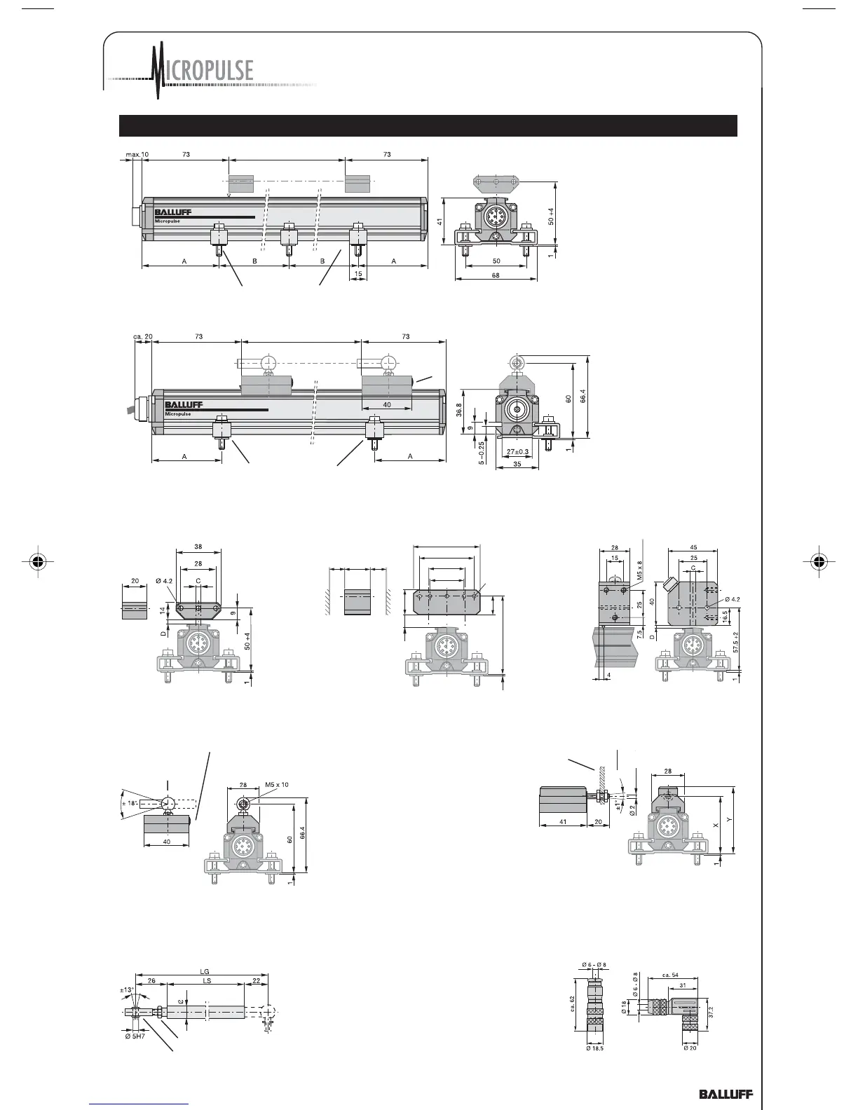
Fig. 3-1: Dimensional drawing
(BTL5...P-S 32 transducer with
floating magnet BTL5-P-3800-2)
Mounting brackets with isolation bushings and M5 x 22 socket head
cap screws, DIN 912, max. tightening torque 2 Nm
NL
Nominal stroke
max. permissible
tightening torque 2 Nm
Fig. 3-2: BTL5-P-3800-2 magnet
Fig. 3-3: BTL5-P-5500-2 magnet
Fig. 3-4: BTL5-P-4500-1
electromagnet (24 V/100 mA)
Nominal stroke
Mounting brackets with isolation bushings and M5 x 22 socket head
cap Sscrews, DIN 912,
max. tightening torque 2 Nm
NL
Black,
round
marking
Magnet
Fig. 3-5: Dimensional
drawing (BTL5...P-KA
transducer with captive
magnet BTL5-F-2814-1S)
Ball joint "B"
DIN 71805,
rotates
horizontally
Black, round
marking
Mechanically
joined to M5 stud
using 2 nuts
Max. angle offset
Max. parallel offset
BTL5-M-2814-1S: X = 48.5 Y = 57
BTL5-N-2814-1S: X = 51 Y = 59.5
Fig. 3-7: BTL5-M/N-2814-1S magnet
Fig. 3-6: BTL5-F-2814-1S magnet
straight
BKS-S 32M-00
right-angle
BKS-S 33M-00
Cable entry
(PG 9 fitting)
Fig. 4-1: Connector (optional)
Fig. 3-8: BTL2-GS08-_ _ _ _-A
connecting rod
Swivel eye DIN 648
Ball joint "B" DIN 71805, rotates
horizontally (part of BTL5-F-2814-
1S) magnet)
Jam nut DIN 934 M5
08
7 Magnet and Control Arm Diagram References
P_Analog_122003.pmd 12/11/2003, 3:59 PM9