WWW.BALLUFF.COM • 1-800-543-8390
3
™
BTL5-A/C/E/G_ _-M/U_ _ _ _-P-S 32/KA_ _
Micropulse Linear Position Transducer
Analog Output/ Profile Housing
2 Function and Characteristics
2.1 Characteristics
Micropulse transducers feature:
— Very high resolution,
repeatability and linearity
— Immunity to shock, vibration,
contamination and electrical
noise
— An absolute output signal
— IP 67 per IEC 529
2.2 Function
The Micropulse transducer
contains a tubular waveguide
enclosed by an extruded
aluminum housing. A magnet
attached to the moving member
of the machine is moved across
the top of the housing and its
position constantly updated.
The magnet defines the
measured position on the
waveguide. An internally
generated INIT pulse interacts
with the magnetic field of the
magnet to generate a magneto-
strictive torsional wave in the
waveguide which propagates at
ultrasonic speed.
The torsional wave arriving atthe
end of the waveguide is absorbed
in the damping zone. The wave
arriving at the beginning of the
waveguide creates an electrical
signal in the coil surrounding the
waveguide. The propagation time of
the wave is used to derive the
position. Depending on the version
the corresponding value is output
as a voltage or a current either with
rising or falling characteristic. This
process takes place with high
precision and repeatability within
the stroke range defined as
nominal stroke length.
On both ends of the nominal
stroke length is an area which
provides an unreliable signal, but
which may be entered.
The electrical connection between
the transducer, the processor/
controller and the power supply is
via a cable, which depending on
the version is either fixed or
connected using a
female connector.
Dimensions for installing the
Micropulse transducer and for the
magnets and control arm are
found on pages 4 and 5.
2.3 Available stroke
lengths and magnets
To provide for optimum fit in any
application, a wide range of stroke
lengths, magnets and mounting
hardware is available. Magnets,
control arms and mounting
brackets must be ordered
separately.
See inside front cover for available
stroke lengths.
3.1 Transducer installation
Any orientation is permitted. The
mounting brackets and cylinder
head screws allow the transducer
to be mounted on a flat machine
surface. These should be evenly
spaced (Figs. 3-1 and 3-5).
The recommended spacing for long
transducers and extreme
conditions (e.g. strong shock or
vibration): A = 80 mm; spacing
between the individual brackets
B = 250 mm.
The isolation bushings are used to
electrically insulate the transducer
from the machine (Fig. 3-1and 3-5
and chapter 5.6 Noise elimination).
The Micropulse transducer in
profile housing is suitable both
for floating, i.e. non-contacting
magnets (Page 4) and for captive
magnets (Page 5).
3 Installation
Micropulse Transducer
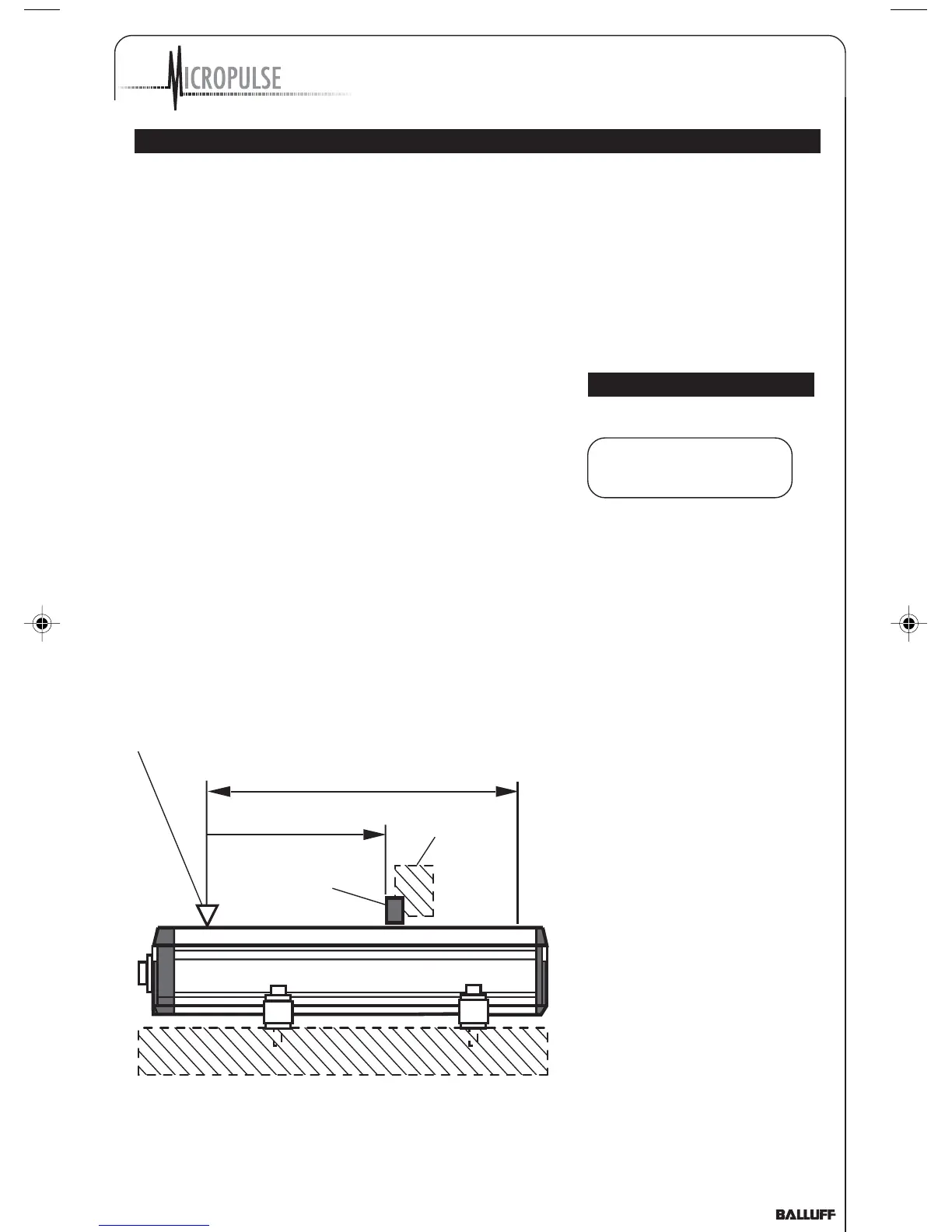
Notch on housing to mark the beginning of the stroke range
Current position of
magnet
Moving
machine part
Nominal stroke = Measuring range
Fig. 2-1: Basic arrangement
Damping zone
El. connection
Ensure that no strong electrical
or magnetic fields are present in
the immediate vicinity of the
transducer.
P_Analog_122003.pmd 12/11/2003, 3:59 PM3