WWW.BALLUFF.COM • 1-800-543-8390
5
™
BTL5-A/C/E/G_ _-M/U_ _ _ _-P-S 32/KA_ _
Micropulse Linear Position Transducer
Analog Output/ Profile Housing
Nominal stroke
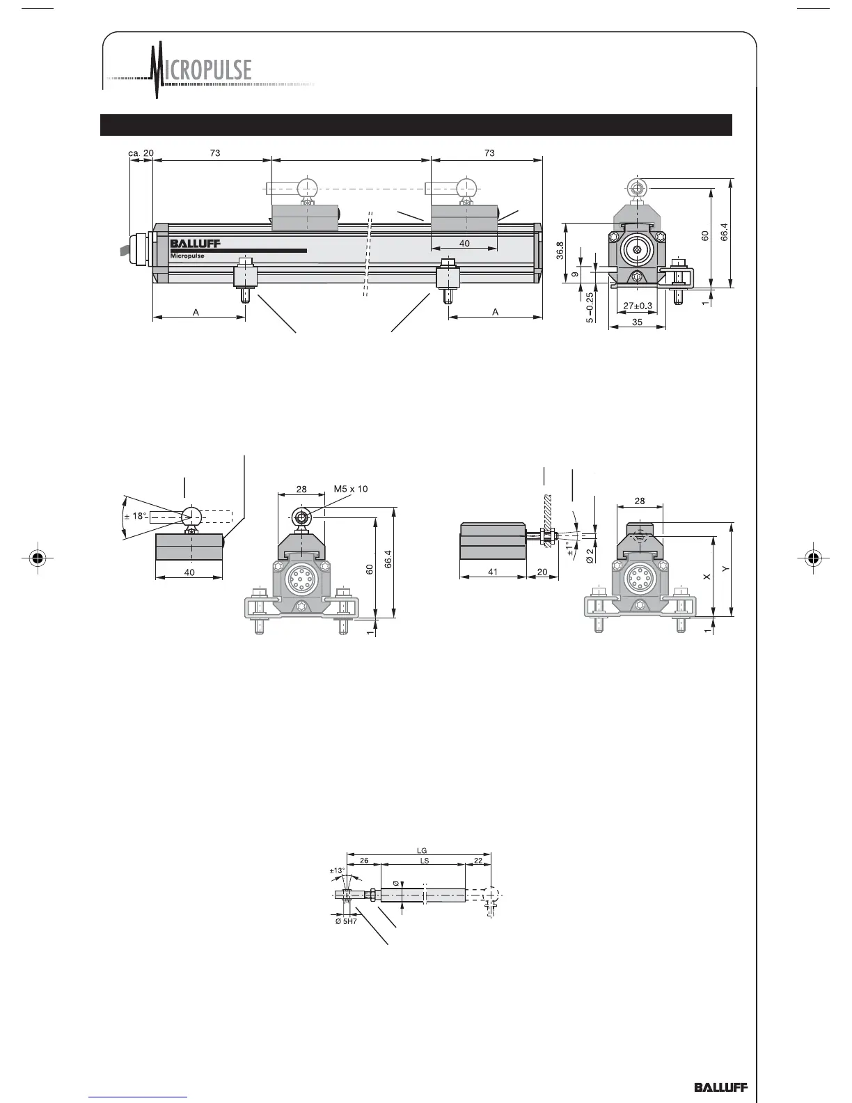
3 Installation (cont.)
Mounting brackets with isolation bushings and M5 x 22
socket head cap screws, DIN 912,
max. tightening torque 2 Nm
NL
Black,
round
marking
Magnet
Fig. 3-5: Dimensional drawing (BTL5...P-KA transducer with captive magnet BTL5-F-2814-1S)
Ball joint "B"
DIN 71805,
rotates horizontally
Black, round
marking
Mechanically joined to M5
stud using 2 nuts
Max. angle offset
Max. parallel offset
BTL5-M-2814-1S: X = 48.5 Y = 57
BTL5-N-2814-1S: X = 51 Y = 59.5
Fig. 3-6: BTL5-F-2814-1S magnet Fig. 3-7: BTL5-M/N-2814-1S magnet
3.3 Captive magnets
Lateral forces are to be
avoided when using captive
magnets (Figs. 3-6 and 3-7).
Connections are required here
which permit the correspond-
ing degree of freedom with
respect to the direction of
movement of the magnet
along the stroke range. It is
assumed that the BTL5-F-
2814-1S magnet is connected
to the machine member using
a connecting rod. The
BTL2-GS08...A connecting rod
(Fig. 3-8) is available as an
accessory (please indicate
length LS when ordering).
Ball joint "B" DIN 71805,
rotates horizontally (part of
BTL5-F-2814-1S magnet)
Fig. 3-8: BTL2-GS08-_ _ _ _-A
connecting rod
Swivel eye DIN 648
Jam nut DIN 934 M5
08
P_Analog_122003.pmd 12/11/2003, 3:59 PM5