1-800-543-8390 • WWW.BALLUFF.COM
6
BTL5-A/C/E/G_ _-M/U_ _ _ _-P-S 32/KA_ _
Micropulse Linear Position Transducer
Analog Output/Profile Housing
™
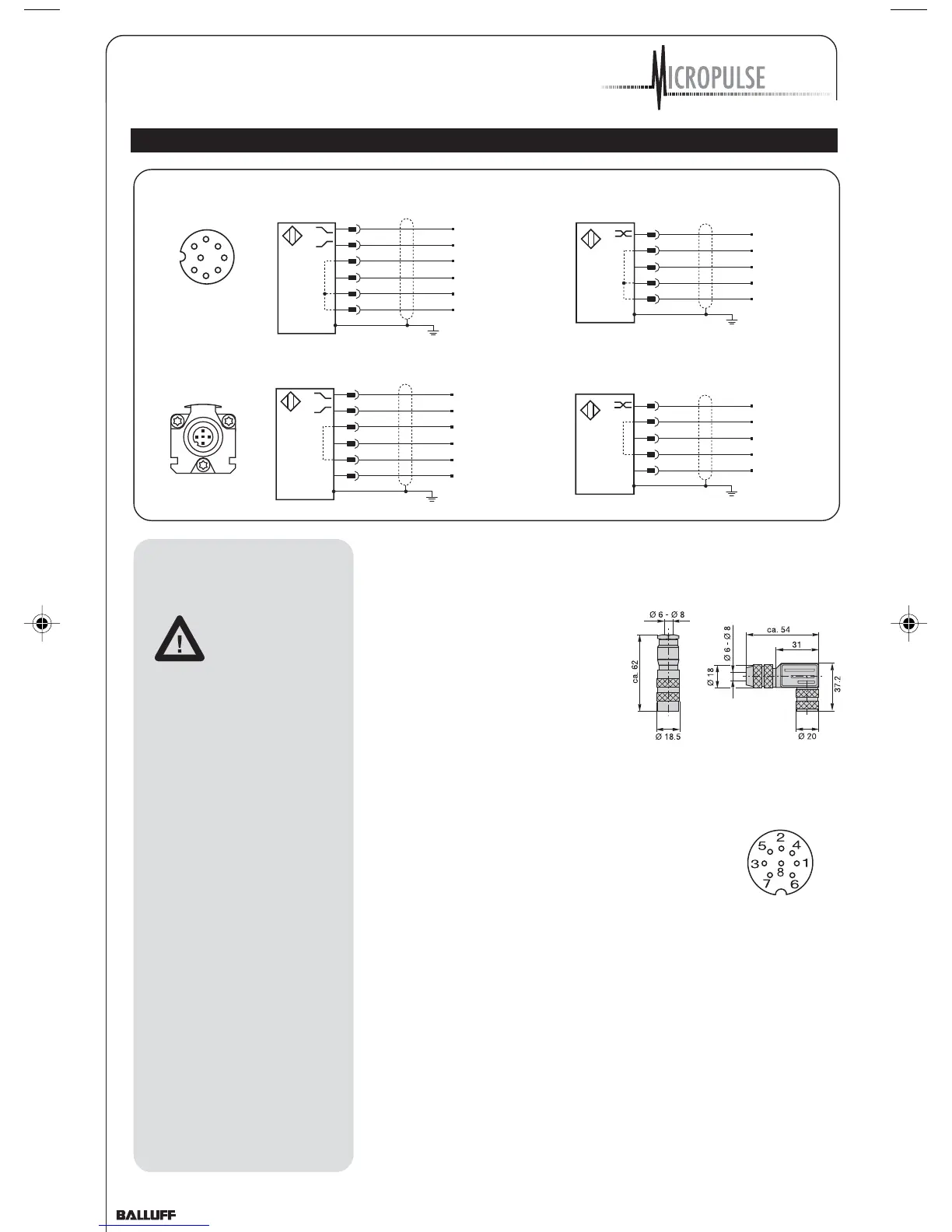
4 Wiring
2 GY
3 PK
5 GN
7 BN
6 BU
8 WH
Analog common
Analog output, falling
Analog output, rising
Analog Voltage
24 V (A, B, G)
+24 V
GND
GND
0117a021
1
2
3
4
5
6
7
8
View of mating
connector, wiring side
2 GY
3 PK
5 GN
7 BN
6 BU
8 WH
Analog common
Analog output, falling
Analog output, rising
Analog Voltage
±15 V (A, B, G)
+15 V
GND
-15 V
0117a022
2 GY
1 YE
7 BN
6 BU
8 WH
Analog common
Analog output
Analog Current
24 V (E, C)
+24 V
GND
GND
0117a023
2 GY
1 YE
7 BN
6 BU
8 WH
Analog common
Analog output
Analog Current
±15 V (E, C)
+ 15 V
GND
-15 V
0117a024
straight
BKS-S 32M-00
right-angle
BKS-S 33M-00
Cable entry
(PG 9 fitting)
Fig. 4-1: Connector (optional)
When routing the cable between
the transducer, controller and
power supply, avoid proximity to
high voltage lines to prevent
noise coupling. Especially critical
is inductive noise caused by AC
harmonics (e.g. from phase-
control devices), against which
the cable shield provides only
limited protection.
Cable length max. 20 m; Ø 6 to
8 mm. Longer lengths may be
used if construction, shielding
and routing are such that external
noise fields will have no effect on
signal integrity.
Note the following when making
electrical connections:
System and control cabinet
must be at the
same ground
potential.
To ensure
electromagnetic compatibility
(EMC), which Balluff verifies by
the CE Marking, the following
points must be strictly
observed.
BTL transducer and the
processor/control must be
connected using shielded cable.
Shielding: Copper filament
braided, 80% coverage.
The shield must be tied to the
connector housing in the BKS
connector (Fig. 4-1); see
instructions accompanying the
connector.
In the cable version the cable
shield is connected to the
housing in the PG fitting.
The cable shield must be
grounded on the control side,
i.e., connected to the protection
ground.
Pin assignments can be found
inthe illustration above.
Connections on the controller
side may vary according to the
controller and configuration
used.
Fig. 4-2: Pin assignments BKS,
connector type BTL
BKS connector,
view towards
solder side of
female
BKS-S 32M-00
or
BKS-S 33M-00
P_Analog_122003.pmd 12/11/2003, 3:59 PM6