WWW.BALLUFF.COM • 1-800-543-8390
7
™
BTL5-A/C/E/G_ _-M/U_ _ _ _-P-S 32/KA_ _
Micropulse Linear Position Transducer
Analog Output/ Profile Housing
4 Wiring (cont.)
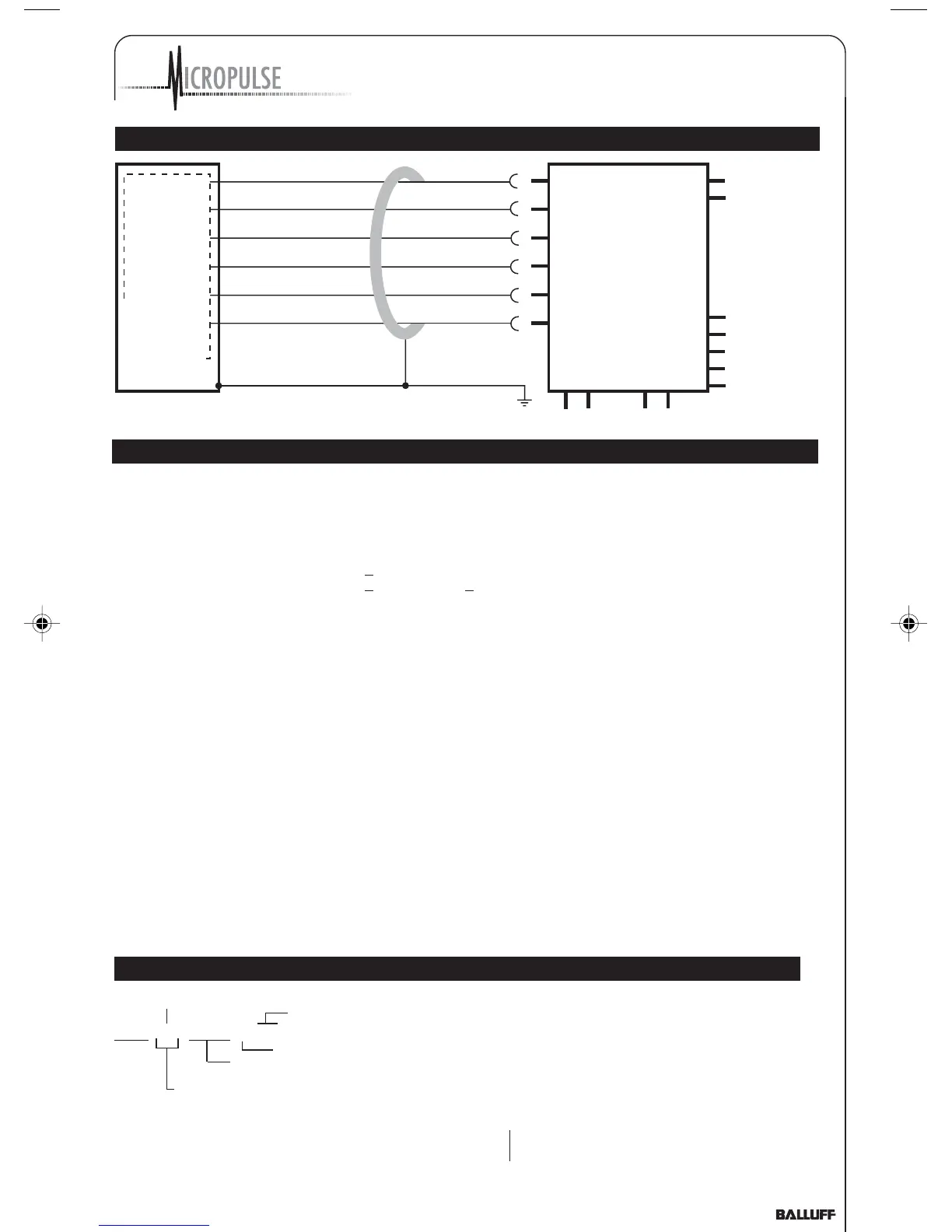
Fig. 4-3: BTL5-E10...KA _ _ with processor card/controller, wiring example
5 Startup
5.1 Check connections
Although the connections are
polarity reversal protected,
components can be damaged by
improper connections and
overvoltage. Before you apply
power, check the connections
carefully.
5.2 Turning on the system
Note that the system may
execute uncontrolled movements
when first turned on or when the
transducer is part of a closed-
loop system whose parameters
have not yet been set. Therefore
make sure that no hazards could
result from these situations.
If there is no magnet in the
stroke range, the integrated
function monitor provides the
following defined output signals:
Voltage output 10 V
increasing decreasing
V
A
> 10 V < 0 V
Current output 20 mA
increasing decreasing
I
A
> 20 mA 0 mA for BTL5-C...
I
A
> 20 mA < 4 mA for BTL5E...
5.3 Check output values
After replacing or repairing a
transducer, it is advisable to verify the
values for the start and end position
of the magnet in manual mode. If
values other* than those present
before the replacement or repair are
found, a correction should be made.
* Transducers are subject to
modification or manufacturing
tolerances.
5.4 Check functionality
The functionality of the transducer
system and all its associated com
6 Versions (indicated on part label)
Supply voltage 1 = DC 24 V, 2 = DC ±15 V
Electr. connection S32: with connector,
BTL5-A11-M0457-P-S32 KA05: with 5 m cable
Profile form factor
Nom. length (4 digits), M = metric in mm
Analog interface: Voltage output A_1 = 10 ... 0 V and 0 ... 10 V
G_1 = 10 ... –10 V and –10 ... 10 V
Current output C_0 = 0 ... 20 mA E_0 = 4 ... 20 mA
C_7 = 20 ... 0 mA E_7 = 20 ... 4 mA
Micropulse
Linear Transducer
YE
GY
PK
GN
BU
BN
4...20 mA
0 V
10...0 V
0...10 V
GND
+24 V
processor/
controller with analog
input
BTL5-E10...KA_ _
ponents should be regularly
checked and recorded.
5.5 Fault conditions
When there is evidence that
the transducer system is not
operating properly, it should be
taken out of service and
guarded against unauthorized
use.
5.6 Noise elimination
Any difference in potential -
current flow - through the cable
shield should be avoided.
Therefore:
- Use the isolation bushings,
and
- Make sure the control
cabinet and the system in
which the BTL is contained
are at the same
ground potential.
Pin assignments BKS,
or type BTL
P_Analog_122003.pmd 12/11/2003, 3:59 PM7