12 english
4
Installation and connection (continued)
4.2.3 Installing the BTL
NOTICE
Interference in function
Improper installation can compromise the function of the
BTL and result in increased wear.
► The mounting surface of the BTL must make full
contact with the supporting surface.
► The bore must be perfectly sealed (O-ring/flat seal).
► Check the suitability of the O-ring for the specific
application.
► If installed in a hydraulic cylinder outside of zone0,
the magnet should not make contact with the rod.
Protect the rod from damage and wear.
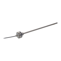
1. Unscrew and remove housing cover.
2. For secure fastening, tighten the BTL with hexagon
socket screws M6x45 A4 or 1/4"-20x1-3/4" at all 6
mounting holes (torque 3.5 Nm or 2.6ft∙lb).
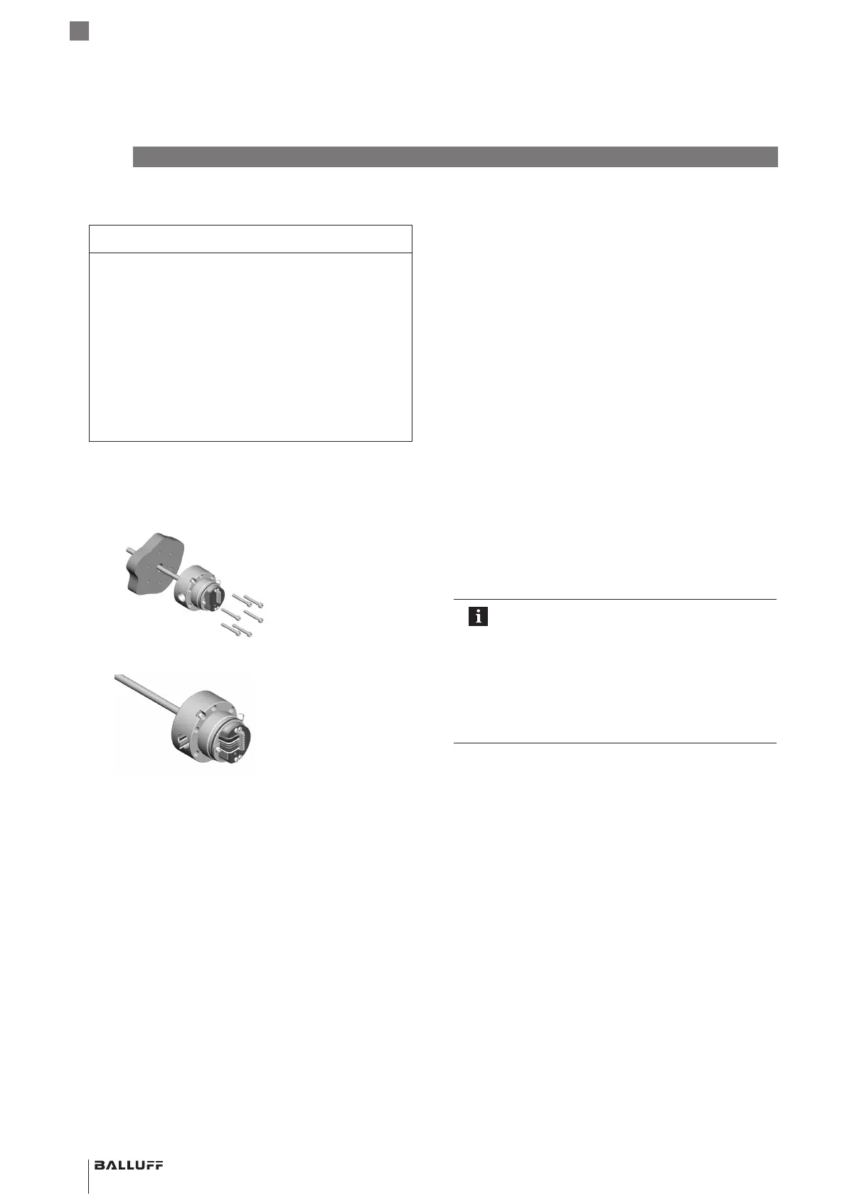
3. Connect wiring (see Electrical connection on page 14).
4. Re-install the housing cover and tighten to 33…40Nm
(25…30ft∙lb). Tighten secondary retaining screws
(ATEX).
► Install the magnet (Accessories).
► From 500mm nominal length: support the rod
and tighten it at the end if necessary.
4.3 Application2: fill level measurement in zone0
(with float, according to Section 12.1)
4.3.1 Preparing for installation
Installation variant: For holding the BTL and float we
recommend non-magnetizable material.
Avoid magnetic field interference at the screw-in thread,
e.g. by the weld seam at the threaded flange!
Install the BTL in such a manner that only the rod extends
into the explosive area of zone0 and the body and
electronics remain behind a separating wall in the explosive
area of zone1.
The spacer ensures that the float does not move into the
damping zone in the bottom end of the rod.
The depth of the mounting hole must be at least 25mm
(see Fig. 4-4).
4.3.2 Installing the linear position sensor
Installing the float
Important notes
– Only the floats listed under Accessories may
be used as magnets in zone0 (see
Section 12.1).
– Design measures ensure that the floats are
electrically connected with the rod in any
position. The specified installation position
must be observed!
– Only use the cotter pin once!
1. Install the float (accessory) taking the orientation into
account (raised markings on top, see Section 12.1).
2. Secure the float using the cotter pin (included in the
scope of delivery of the float), without placing any
mechanical loads on the rod. Insert the cotter pin
through the hole and hold it at the eye with a pair of
pliers. With a second pair of pliers, bend the straight
ends of the cotter pin around the rod one after another.
BTL7-A/C/E/G5_ _-M_ _ _ _-J-DEXC-TA12
Magnetostrictive Linear Position Sensor – Rod Style
Type of protection “db” and “ta”
Flameproof enclosure
 Loading...