www.balluff.com 11english
4.1 Minimum distance to fixed obstacles
During installation, make sure that there is a minimum
distance between the BTL housing and fixed obstacles,
such as protective covers. The required distance is
specified in EN 60079-14 and depends on the applied gas
group.
Fig. 4-1: Minimum distance
4.2 Application1: outside zone0
(with magnet in accordance with Section 12.2)
4.2.1 Installation guidelines
Non-magnetizable material
Fig. 4-2:
≥ Ø13
Magnet
Installation in non-magnetizable material
Magnetizable material
If using magnetizable material, the BTL must be protected
against magnetic interference through suitable measures
(e.g. spacer ring made of non-magnetizable material, a
suitable distance from strong external magnetic fields).
15
8
Spacer ring made of non-magnetizable
material
Magnet
≥ Ø13
15
8
Spacer ring made of non-magnetizable
material
Magnet
Fig. 4-3: Installation in magnetizable material
4
Installation and connection
4.2.2 Preparing for installation
Installation note: We recommend using non-
magnetizable material to mount the BTL and magnet.
Horizontal assembly: For horizontal assembly with
nominal lengths > 500 mm, support the rod and tighten it
at the end if necessary.
Hydraulic cylinder: If installed in a hydraulic cylinder,
ensure that the minimum value of 13 mm for the bore
diameter of the support piston is complied with.
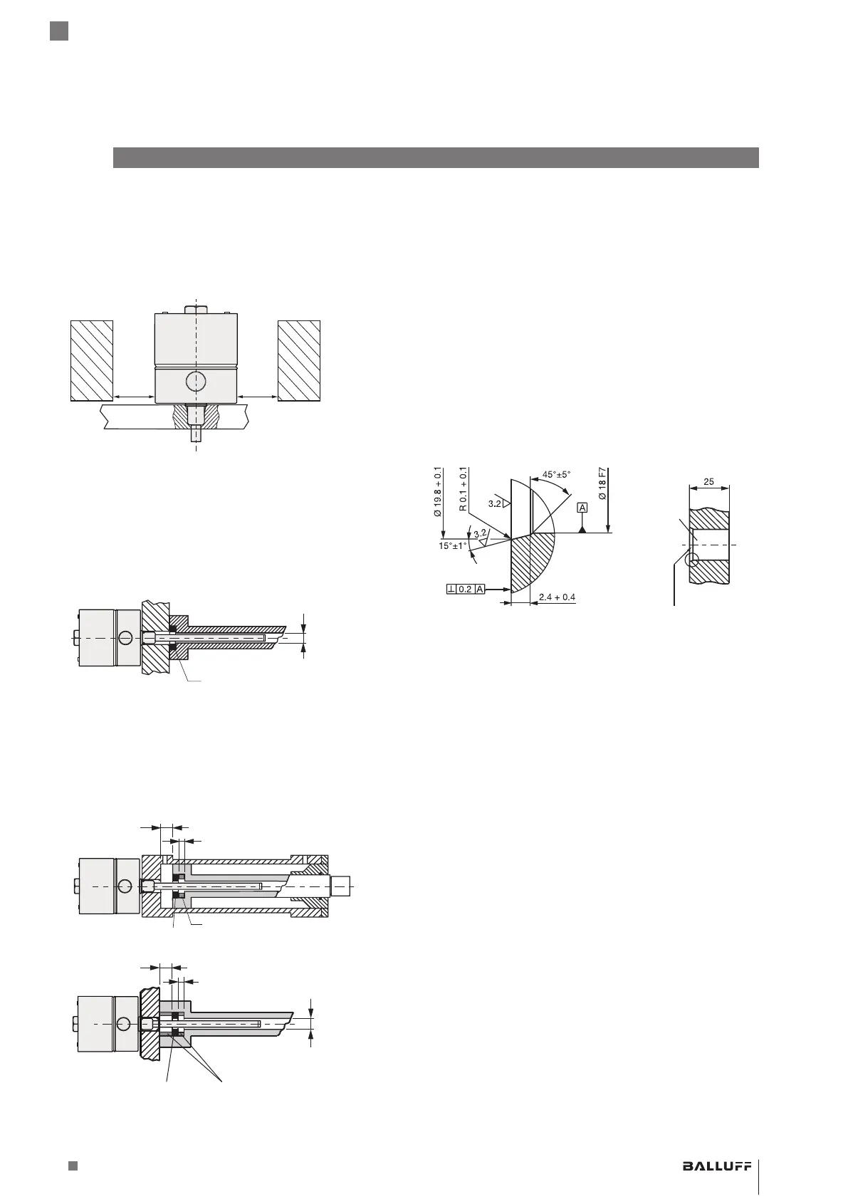
Fitting bore: The mounting surface of the BTL must make
full contact with the supporting surface. A suitable O-ring
must completely seal the bore, i.e. the countersink for the
O-ring must be produced according to Fig. 4-4.
Fig. 4-4:
Fitting bore
Bevel for O-ring 15.4x2.1
Fitting bore for installing the BTL with O-ring
Magnet: Various magnets are available for the BTL (see
Accessories on page 28).
BTL7-A/C/E/G5_ _-M_ _ _ _-J-DEXC-TA12
Magnetostrictive Linear Position Sensor – Rod Style
Type of protection “db” and “ta”
Flameproof enclosure
 Loading...