www.balluff.com 13english
4
Installation and connection (continued)
Installing the BTL
DANGER
Explosions
Electrostatic charging and opening the housing can result
in sparks which can trigger explosions in explosive
atmospheres.
► Only the rod section of the BTL may extend into
zone 0.
► If the device rod is to be used in zone0, a potential
difference between system parts resulting from
electrostatic charging must be prevented. The float
is thus designed in a manner where it tilts if installed
properly and always maintains contact with the rod.
This feature may not be impaired by the manner of
installation. Only floats mentioned under Accessories
may be used.
► The relevant Ex regulations must be observed to
ensure safe separation between zone0 and zone1.
The BTL must be installed in a manner that will result
in a sufficiently tight joint (IP67) or flameproof joint
(IEC/EN60079-1) between the less hazardous area
and zone 0.
► Do not open housing when an explosive atmosphere
may be present!
NOTICE
Interference in function
Improper installation can compromise the function of the
linear position sensor and result in increased wear.
► Only vertical mounting from above is permitted!
► The mounting surface of the BTL must make full
contact with the supporting surface. A suitable
O-ring must completely seal the bore, i.e. the
countersink for the O-ring must be produced
according to Fig. 4-4.
► Check the suitability of the O-ring for the specific
application.
► Mounting must be done in a manner where the rod
cannot touch the container wall. Deflection of the
rod to the side, e.g. through flow currents, must
be prevented by a suitable bracket or appropriate
positioning in the tank.
► Mechanical loads may not be placed on the weld
seam at the end of the rod!
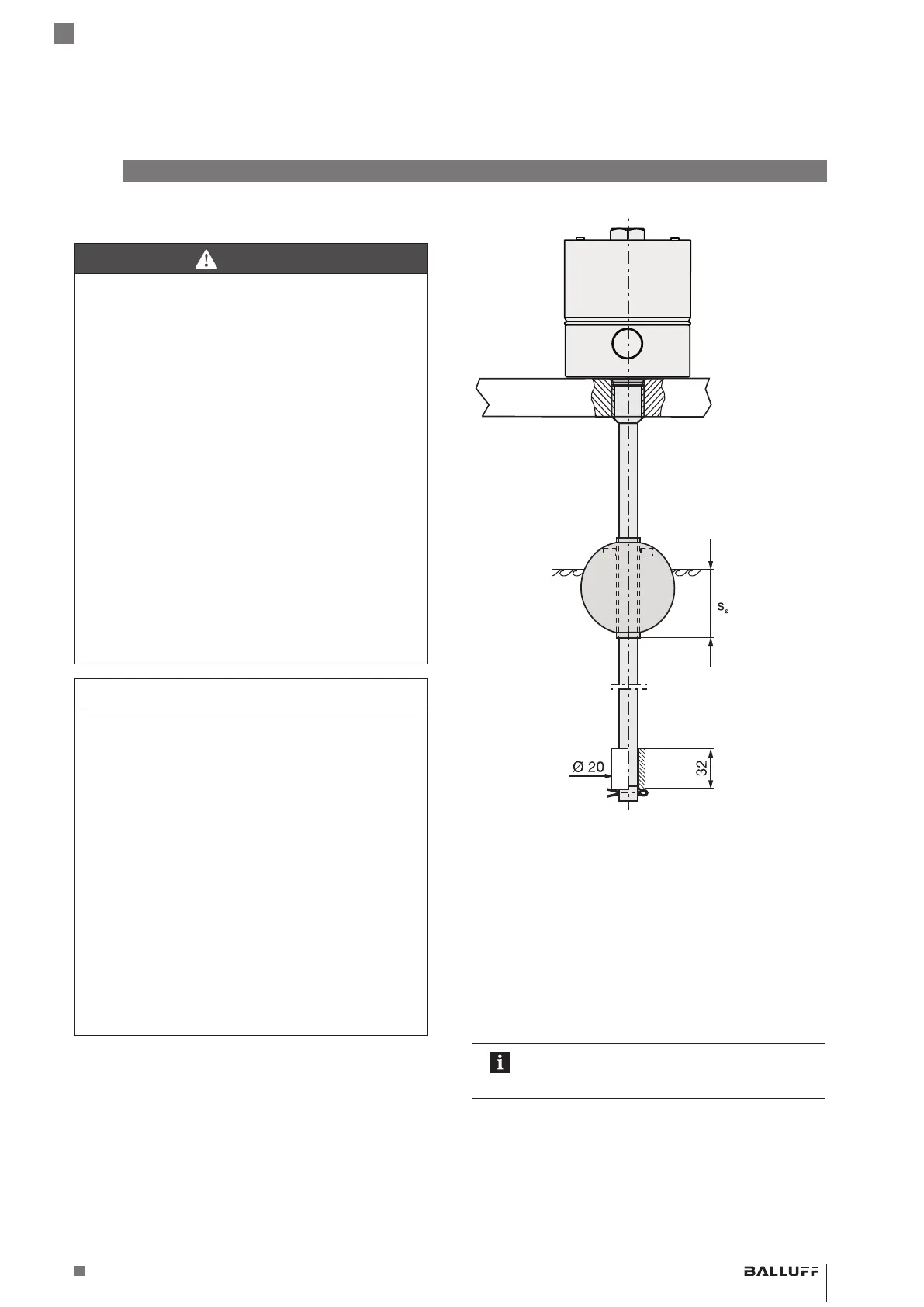
Fig. 4-5: BTL installation,
application 2: fill level measurement
Zone carryover:
If the device rod is to be used in zone0, a potential
difference between system parts resulting from
electrostatic charging must be prevented. The float is thus
designed in a manner where it tilts if installed properly and
always maintains contact with the rod. This feature may
not be impaired by the manner of installation. The relevant
Ex regulations must be observed to ensure safe separation
between zone0 and zone1.
Adjustment aids may not be used in explosive
areas and must be removed before
recommencing normal operation of the BTL.
Zone 1
Separating area
Zone 0
Spacer,
1.4301
Immersion depth S
S
of the float (see
Accessories)
Cotter pin,
DIN94–3.2×20 – 1.4301
BTL7-A/C/E/G5_ _-M_ _ _ _-J-DEXC-TA12
Magnetostrictive Linear Position Sensor – Rod Style
Type of protection “db” and “ta”
Flameproof enclosure